Wire gauge and torque requirements, Grounding – Xantrex Technology PV225S-480-P User Manual
Page 60
Installation
3–12
152606
Wire Gauge and Torque Requirements
Table 3-1 provides acceptable wire gauges, bolt sizes, and torque values for AC
terminal connections.
Table 3-2 provides acceptable wire gauges, bolt sizes, and torque values for DC
terminal connections.
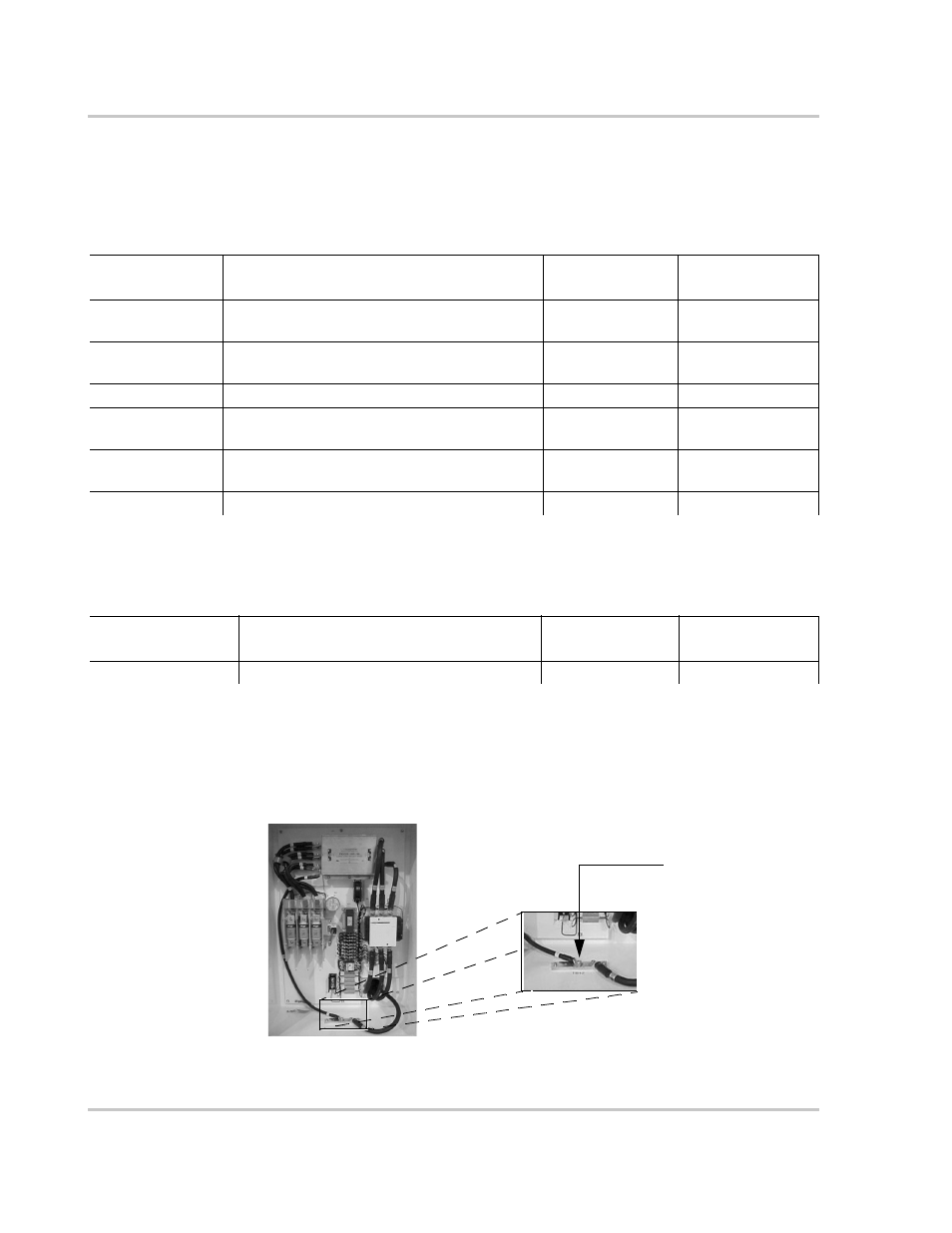
Grounding
System Grounding
Install a copper ground rod within three feet of the PV225S enclosures per the
National Electric Code ANSI/NFPA 70. The single-point ground for the system is
to be made at the AC ground bar (TB12) in the AC Interface Enclosure.
Table 3-1 AC Terminal Wire Gauge, Bolt Size, and Torque Values
AC Terminal
Connections
Acceptable Wire Size Range
(both models)
Bolt (Hardware)
Size
Torque
Requirements
TB1
(Chassis Ground)
500MCM to #4 AWG (1 stud per pole)
3/8-16
420 in-lb (47.5 Nm)
TB12
(System Ground)
500MCM to #4 AWG (1 stud per pole)
3/8-16
420 in-lb (47.5 Nm)
TB11 (Neutral)
500MCM to #4 AWG (1 stud per pole)
3/8-16
228 in-lb (25.7 Nm)
S1-2T1, S1-4T2,
S1-6T3
350MCM to #6 AWG (1 stud per phase)
M10 (See Caution
on page 3–18)
310 in-lb (35.0 Nm)
T6-X1, T6-X2,
T6-X3
350MCM to #6 AWG (2 studs per phase)
3/8-16
420 in-lb (47.5 Nm)
TB5, TB6, TB7
350MCM to #4 AWG (6 openings per phase)
3/8 Hex
375 in-lb (42.4 Nm)
Table 3-2 DC Terminal Wire Gauge, Bolt Size, and Torque Values
DC Terminal
Connections
Acceptable Wire Size Range
(both models)
Bolt (Hardware)
Size
Torque
Requirements
S2-6, K2-6T3, TB4
600MCM to #4 AWG (2 openings per pole)
1/2 Hex
600 in-lb (67.8 Nm)
Figure 3-10 Single-point Ground (TB12) Ground Bar
AC Ground Bar
(TB12) to be used
for the Single Point
Ground
AC Interface Enclosure