Conduit penetration – Xantrex Technology PV225S-480-P User Manual
Page 42
Planning
2–8
152606
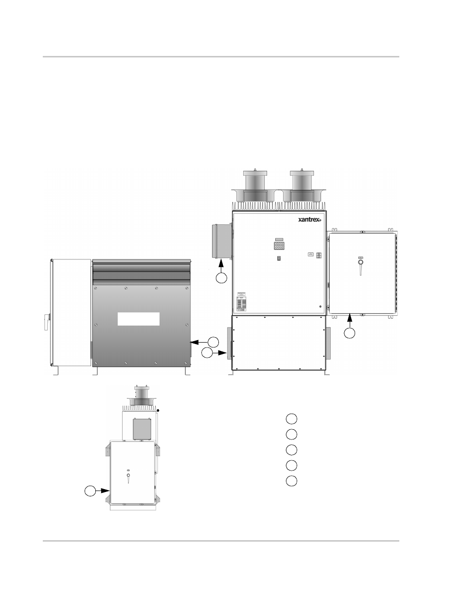
Conduit Penetration
The following illustrations show the recommended locations for electrical conduit
entry into the PV225S enclosures. These drawings are to be used for system
planning purposes, such that the shaded areas are representative of the maximum
allowable area and location in which electrical conduit may penetrate the
enclosures of the PV225S, see Figure 2-3 through Figure 2-8. Xantrex
recommends a standard trade-size conduit knock-out set for cutting/punching the
PV225S enclosures and panels for conduit entry.
Figure 2-3 Conduit Entry Figure Reference
Figure 2-4 on page 2–9
Figure 2-8 on page 2–10
A
B
C
D
E
Figure 2-5 on page 2–9
Figure 2-6 on page 2–10
Figure 2-7 on page 2–10
A
D
E
Front view of PV225S
B
C
AC Interface
Enclosure
AC Interface
Enclosure
Transformer
Enclosure
Main Inverter
Enclosure
Inductor
Enclosure
DC Interface
Enclosure
AC side view
of PV225S