Anchoring the pv225s – Xantrex Technology PV225S-480-P User Manual
Page 47
Anchoring the PV225S
152606
2–13
Using the "Over 2 Wires" column per NEC Chapter 9, Table 4, (Ninth Edition)
indicates that the following minimum permitted conduit trade size is acceptable
for the 21 wires in this exercise:
EMT = 3 ½" Trade size
IMC = 4" Trade size
RMC = 4" Trade size
Anchoring the PV225S
The PV225S is designed to be installed in either an indoor or outdoor location. It
must be placed on and anchored to a level concrete floor or pad. The concrete
floor or pad, upon which the PV225S is anchored, must be structurally designed to
meet any local, state, or national requirements for weight, seismic, and wind sheer
if applicable.
Four 5/8" holes are provided in the feet of the main inverter, and six 5/8" holes are
provided in the feet of the AC interface/transformer assembly for anchoring to the
floor or pad.
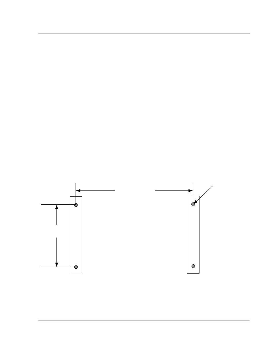
Figure 2-9 and Figure 2-10 depict the layout patterns of the anchoring holes for
both the PV225S main inverter and the AC interface/transformer assembly.
Figure 2-9 Main Inverter Anchor Bolt Pattern (Not to scale)
23 ¼"
(59 cm)
5/8"
(1.5 cm)
(x4)
(43 1/8”)
(110 cm)