Watlow Electric Gateway & DeviceNet User Manual
Page 8
RUI/Gateway & DeviceNet
TM
Configuration & Ladder Logic Example
Using an Allen-Bradley CompactLogix PLC
Watlow
1241 Bundy Blvd
Winona, MN 55987
Telephone: 507-494-5656
© 2007 Watlow Electric Mfg Co 8
4/08
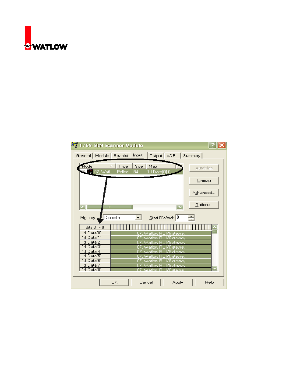
15. Once the available device (RUI/Gateway in this case) is moved over to the Scanlist the next
step will be to map the RUI/Gateway input and output bytes to PLC addresses; first the
inputs. In this particular case the Automap on Add box was checked and the result of that now
becomes apparent. Since there were no other devices on the network the software simply
took all of the available RUI/Gateway input bytes (84) and allocated them to the first available
PLC input bytes. Although we can’t see in the graphic below all of the addresses assigned
you can trust that what was assigned are addresses 1:I.Data[0] through 1:I.Data[20]. If there
were other devices on the network and the Automap on Add box was not checked the
address field below would not be populated. Clicking on the Advanced button would then
allow for manual configuration.
16. Likewise, all of what was said above regarding the inputs also applies to the outputs as well.
Notice in the graphic below that for the outputs the size changes to 80 bytes or 20-32 bit
words and addresses given would be 1:O.Data[0] through 1:O.Data[19]. Click on the OK
button where you will then be prompted to write this configuration to the scanner memory.