Ab c, Figure 4-11, Thermostat – Whirlpool 4322452 User Manual
Page 51: Figure 4-12
Page 4-7
BR
OIL
200 250
300
350
400
450
500
550
OFF
BR
OIL
200
250
300
350
400
450
500
550
OFF
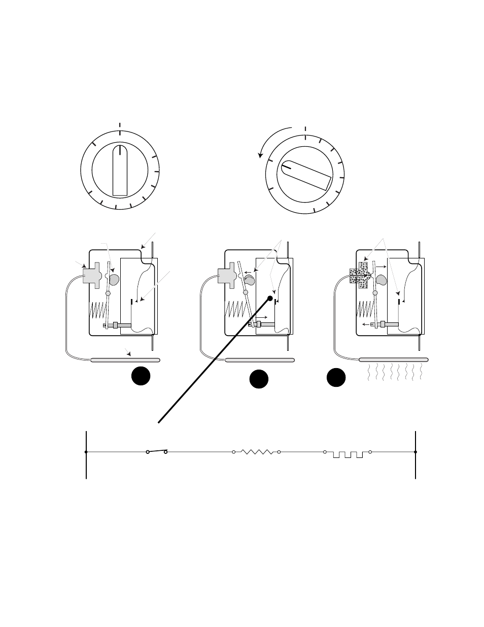
1. Oven Off
Switch Open
2. Oven On
3. Oven Temp Reached
Pressure Expands Sensor Actuator
& Pushes Against Switch Actuator
- Switch Opens - Oven Turns Off
Switch
Contacts
Oven
Thermostat
Shaft
Sensing Bulb
200˚ Heat From Oven
Sensor
Actuator
Shaft Rotates Against
Actuator - Switch Closes
A
B
C
Figure 4-11
The
Thermostat
contains a set of contacts that open and close, (see Figure 4-11A), depending
on the temperature selected by the customer, and the temperature monitored in the oven cavity.
When the thermostat is turned to the “ON” position, contacts within the thermostat close to
complete an electrical circuit (see Figure 4-11B). As the oven heats up to a selected temperature,
the internal pressure within the sensing bulb increases until the thermostat contacts are forced
open (see Figure 4-11C).
As the oven cools, the pressure from the sensor actuator decreases, and the thermostat contacts
close. This cycling of the contacts opening & closing continues until the cooking function is
complete. The electrical contacts of the thermostat complete an electrical circuit through the ignitor
and safety valve to the neutral side of the 120-volt circuit (see Figure 4-12).
Thermostat
Switch Contacts
Safety Valve
Oven Ignitor
N
L1
Figure 4-12