Rs-232 controller connection, Figure 3-12 . rs-232 control system connection, Connecting to the 12-volt trigger output – Vidikron DLP 40828 User Manual
Page 37: 12. rs-232 control system connection, 13. connecting the 12-volt trigger output, Pre l iminar y
Vidikron Vision Model 10/Model 12 Owner’s Operating Manual
27
PRE
L
IMINAR
Y
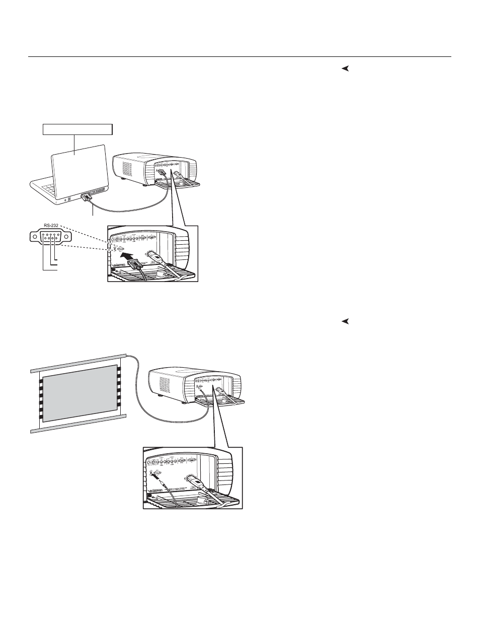
RS-232 Controller
Connection
Use a standard, 9-pin RS-232 cable to connect a PC or home theater control/automation
system (if present) to the RS-232 port on the Vision 10/12; see Figure 3-12.
For more information about using this connection, refer to Serial Communications on
page 55.
Figure 3-12. RS-232 Control System Connection
Connecting to the 12-Volt
Trigger Output
If your home theater contains equipment that responds to a 12-volt trigger (such as a
retractable screen), connect it to the 12-volt trigger output as shown in Figure 3-13.
Figure 3-13. Connecting the 12-Volt Trigger Output
2 Transmit Data
3 Receive Data
5 Ground
(none of the other pins are used)
Notebook Computer
RS-232 9-pin cable, straight-through
Retractable Screen (or other
12-Volt trigger-activated
device)