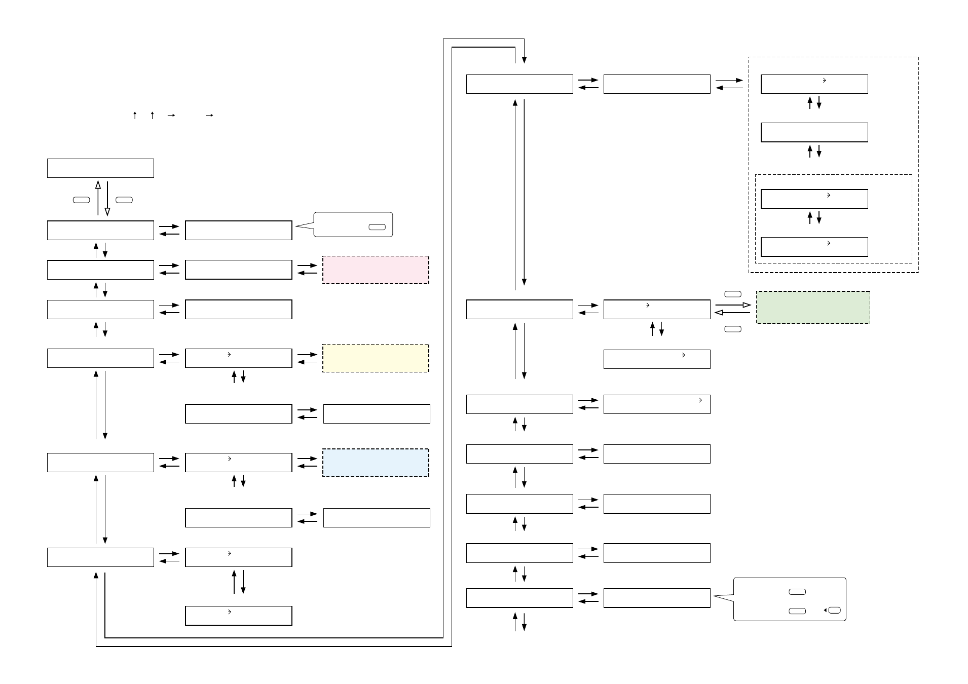
Utility setting, Setting flow chart – Vax M-9000 User Manual
Page 55
Control input terminal function
display
C I N 0 1 I N F -
N O N E
C O U T 0 1 I N F - N O N E
Control output terminal function
display
S T E R E O L I N K
O U T 1 2
Stereo link setting
P A G I N G
O F F
Paging ON/OFF setting
N O M A T T E N U A T E
0
NOM attenuation setting
Control output terminal number
selection
C - O U T
0 1
N O N E
Control input terminal
C - I N
Control input terminal status
display
C - I N =
_ _ _ _ _ _ _ _ _ _ _ _
Control output terminal status
display
C - O U T =
_ _ _ _ _ _ _ _ _ _ _ _
S T E R E O
L I N K
Stereo link
Normal use state
P A G I N G
Paging
N O M
NOM
Control output function
C - O U T
M O D U L E
Module
Firmware version
V E R S I O N
M E M O R Y
Memory
Stereo link setting
Control input function setting
Control output function setting
Paging setting
Communication speed
R S - 2 3 2 C
Communication speed (bps) setting
S E R I A L S P E E D =
5 7 6
.
Control input terminal number
selection
C - I N 0 1
–
N O N E
– – –
S E T P A S S W O R D
_ _ _ _
GATE release time
G A T E
T I M E
GATE release time setting
G A T E
R E L E A S E T I M E
5
Key lock
K E Y L O C K
K E Y L O C K
U N L O C K E D
S L O T
1
=
O T H E R S
Slot number selection,
900 series module classification setting
F I R M
V E R S I O N = 1 1 0
.
I N I T I A L I Z E
O K ?
Remote
R E M O T E
Remote controller type setting
R E M O T E 1
V O L U M E
Remote-controlled channel setting
R E M O T E 1
O U T P U T 1
(when the remote controller type is set to VOLUME
and ZM-9002)
A N C
ANC monitor
ANC monitor switching ON/OFF setting
A N C M O N
S E L E C T =
O N
Monitor switching control input terminal setting
(When the ANC monitor switching is set to ON)
M O N
S E L E C T
C I N 0 1
Interlock output control setting
M O N
S E L
S Y N C
O N
Interlock output terminal setting
Monitored ANC input channel selection
(When the interlock output control is set to ON)
S E L E C T S Y N C
C O U T 0 1
S E L E C T S Y N C
A N C 1
UTILITY
MEMORY
ENTER
ESC/BACK
To determine,
ENTER
To determine,
ENTER
or
To cancel,
ESC/BACK
55
10.5. Utility Setting
10.5.1. Setting flow chart
The screen display examples shown below may differ from actual displays.
The on-screen indications shown in red here (actually shown by flashing cursors) are parameters or
setting contents to be selected with the Parameter setting knob, input channel selection key or other
designated keys.
The indications of the [ ], [ ], [
], and [
] arrows represent that the screen is switched with the
Screen shift key.
Unless otherwise specified, use the Parameter setting knob for each parameter selection.