Mounting bracket, Hood preparation, Installation – Viking F20560 User Manual
Page 5: Non-ducted configuration), Mounting bracket)
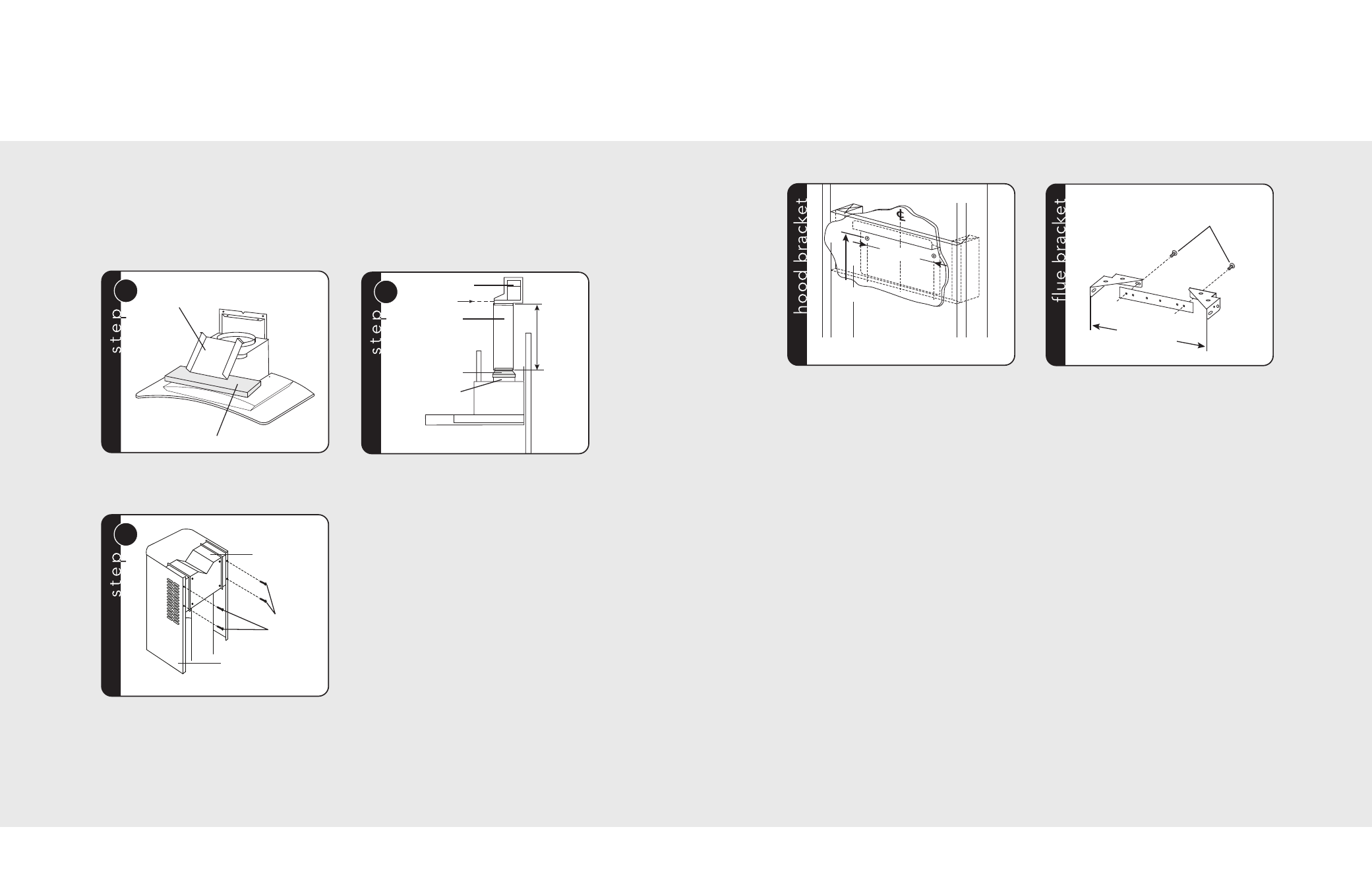
Hood Preparation
(Non-Ducted Configuration)
8
Note: The following materials must be purchased separately for non-ducted recirculation installations.
• Non-Ducted Recirculation Kit. (Model DGRK).
• 5” diameter expandable/flexible aluminum duct.
• 1/16” diameter twist drill.
CAUTION: DO NOT use plastic or metal ducting.
1
Electrical
system plate
Protection
2
A
Plenum
(3) screws
5” aluminum
flex duct
5”-6” adapter
Blower collar
Remove the tape on the electrical system plate;
place the electrical system plate on the hood
(use a protection).
Discard discharge collar and damper supplied with the
hood. Install the 5” to 6” adapter supplied with the
Non-Ducted Recirculation Kit. Measure distance “A.”
Attach aluminum flexible duct to the 5” adapter. Tape
all joints with duct tape. Assemble the recirculation
plenum to the flex-ducting. Drill three 1/16” diameter
equally spaced holes through the duct and duct
connector of the recirculation plenum. Secure duct to
the plenum’s connector with three sheet metal screws
(not included). Tape all joints with duct tape. Carefully
place the lower decorative flue into the recessed area
of the range hood top. Carefully slide the upper
decorative flue down inside the lower flue.
Note: Air vents must be up.
3
Plenum
4 flat
head
screws
Upper flue
Secure the recirculation plenum to the
upper flue with four flat head screws.
1. Construct wood wall framing that is flush with
interior surface of wall studs.
Make sure:
a) the framing is centered over installation
location.
b) the height of the framing will allow the
mounting bracket to be secured to the
framing within the dimensions shown.
2. After wall surface is finished, secure mounting
bracket to framing using dimensions below.
• 36-13/16”=bottom of hood 24” above
range top
• 42-11/16”=bottom of hood 30” above
range top
1. Assemble the flue mounting bracket, adjusting
outside width as shown.
2. Carefully center the mounting bracket directly
over the range hood location.
3. Secure the bracket assembly to the ceiling
using two 4.8 x 38 mm mounting screws and
drywall anchors. Make sure the bracket is
pushed into the corner, tight against the wall,
and centered over the hood.
9
36-13/16”= bottom of hood 24” above range top
42-11/16”= bottom of hood 30” above range top
Framing behind drywall
5-1/16”
36-13/16”
to 42-11/1
6”
above coo
ktop
3.9 x 6 mm flat head
bracket screws
10-7/16”
(265.6 mm)
(Mounting Bracket)
Installation