Toastmaster TP224 EN User Manual
Page 2
2
II. INSTALLATION
IMPORTANT
IT IS THE CUSTOMERS RESPONSIBILITY TO REPORT ANY
CONCEALED OR NON-CONCEALED DAMAGE TO THE FREIGHT
COMPANY.
A. Installation Options and Kit Availability
Two-slot toasters (TP209/224) are to be installed on a countertop, as
described in Part B, Electrical Utility Connection, below.
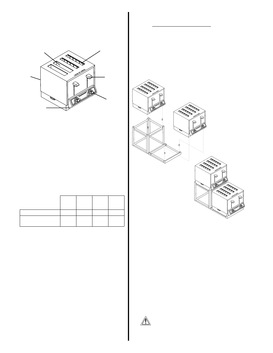
Four-slot toasters (TP409/424/430, HT409/424, BTW09/24) may be in-
stalled EITHER on a countertop, OR on the four-slot toaster stand shown
in Figure 2, below. The stand (Toastmaster P/N 1D3CS) is not included
with your toaster, but is available separately.
To install the toaster on a countertop, follow the instructions in Part
B, Electrical Utility Connection, below.
To install the toaster on a stand, follow the assembly instructions
included with the stand kit. Then, proceed to Part B, Electrical
Utility Connection.
B. Electrical Utility Connection
1.
Position the toaster in place.
2.
Before proceeding with the electrical connection, check the following:
a.
Check that the electrical supply matches the toasters
requirements. Refer to the toasters data plate (at the lower
rear of toaster - see Figure 1), and to the electrical specifications
provided on the wiring diagrams at the back of this Manual.
b.
Check that the appropriate receptacle is available for the power
cord plug.
c.
Check that the main electrical supply source is turned OFF.
CONSULT ALL APPLICABLE NATIONAL AND LOCAL CODES
FOR FURTHER ELECTRICAL CONNECTION REQUIREMENTS.
WARNING
ENSURE THAT ANY PACKING MATERIAL RESIDUE HAS
BEEN REMOVED FROM INSIDE THE TOASTING
CHAMBER.
3.
Insert the power cord plug into its receptacle.
I. DESCRIPTION AND SPECIFICATIONS
A. Component Location
The major components of the toaster are shown in Figure 1 below.
1. Color
selection
knob
2. Operating
lever
3a. Standard slot
B. Component Function (see Figure 1)
1.
Color selection knob - see Section III, Operation.
2.
Operating lever - see Section III, Operation.
3a. Standard slot - 1-1/8/29mm wide, these slots can accomodate
Texas Size bread, frozen waffles, English muffins, etc.
Heating elements are located on both sides of the slot.
3b. Extra-wide slot - 1-5/8/41mm wide, these slots can
accomodate bagels and thick English muffins. A heating
element is located on one side of the slot, permitting one-sided
toasting.
4.
Data plate - Provides manufacturing and electrical information.
5.
Crumb tray - Collects crumbs from the toasted product. The
tray can be removed for cleaning.
C. Toaster Information
Slot information:
TP209, TP409, HT409, BTW09,
TP224
TP424,
HT424
BTW24
TP430
Standard slots
2
4
2
0
Extra-wide,
one-sided slots
0
0
2
4
NOTE
Electrical specifications are provided on the wiring diagrams at the
back of this Manual.
Figure 1
4. Data plate
(not shown -
at lower rear
of toaster)
5. Removable
crumb tray
3b. Extra-wide,
one-sided slot
(model HT409/424 shown)
Figure 2 - Four-slot toaster stand,
Toastmaster P/N 1D3CS
Available separately