Toshiba 48-1250 A User Manual
Page 17
TD - Series
- 11 -
TD Series
Digital Solid State Soft Starter 48 - 1250A
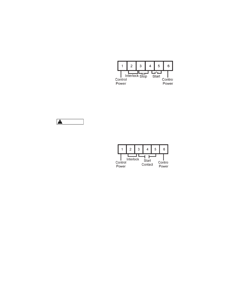
For standard 3-wire control connect 120VAC to pins 1 and 6 of TB1. Connect
N.C. (normally closed) stop button between pins 3 and 4 of TB1. Connect N.O.
(normally open) start button between pins 4 and 5 of terminal block TB1.
4.2.3 Two-Wire Connection
An alternate connection for unattended operation replaces start/stop push buttons
by connecting a maintained contact closure between pins 3 and 5 on TB1. When
the maintained contact is used for start/stop it is necessary to set the overload
relay to the manual reset position. This will prevent the motor from restarting if
the thermal overload trips and then cools off.
When two-wire connection method is used, the user’s control circuit
must be interlocked to prevent automatic restart when protective
devices reset. Refer to section 3.1.3.b.
4.2.4 Relay Contacts
All the relay contacts are FORM C common (N.O., N.C.), except the optical
triac output. TOSHIBA recommends fusing all contacts with external fuses. TB2
is the terminal block for all auxiliary contacts. Each contact is explained in the
following sections. See Chapter 9 for main control board layout.
4.2.5 Programmable Relays
Three programmable relays are on TB2 which is located on the main control
board. The relays are rated for 240 VAC, 5 A and 1200 VA.
Factory settings for these relays are:
AUX 1 - Run / Stop (F050 = 1)
AUX 2 - At Speed / Stop (F051 = 2)
AUX 3 - Any Trip (F052 = 14)
Two-Wire Connection
TB1
Three-Wire Connection
TB1
4.2.2 Three-Wire Connection
WARNING