Tyan Computer S1854 User Manual
Page 18
http://www.tyan.com
18
Chapter 2
Board Installation
1-G Soft Power Connector
The Soft Power Connector is part of jumper block J16. The Trinity 400 uses the
chipset for power management, including turning on and off the system. If the
Power Button Function option in the BIOS Power Management Menu is set to
On/Off (which is the default), pressing the power button once after the BIOS
has booted up will turn the system on and off. If the Power Button Function
option is set to Suspend, pressing the power button once will wake the system
or send it to Suspend mode. In this case, you cannot turn the system off
unless you shut down through the Windows operating system or you hold the
power button down for four seconds.
1-H Hardware Reset Switch Connector Installation
The Reset switch on your cases display panel provides you with the Hard-
ware Reset function, which is the same as power on/off. The system will do a
cold start after the Reset button is pushed. (J16 pin 7 & 8)
1-I Creative Labs Audio Connectors (optional)
There are four black 4-pin
connectors onboard which are
used for various peripherals
audio signals. The digital signal
that comes in through these
connectors is directed through
the Creative Labs ES1373 PCI
sound chip, and the digital signal
is turned into an audio signal
which goes out through the
speaker. The TDA connector
(J21) is for modem audio; the
VIDEO connector is (J22); the CD
connector (J23) is for CD-ROMs.
1-J Chassis Intrusion Alarm Connector
The J7 connector is an intrusion alarm, that can be connected to the system
chassis. When active (J7 is connected to the chassis), this alarm will alert the
system administrator anytime someone opens the systems case.
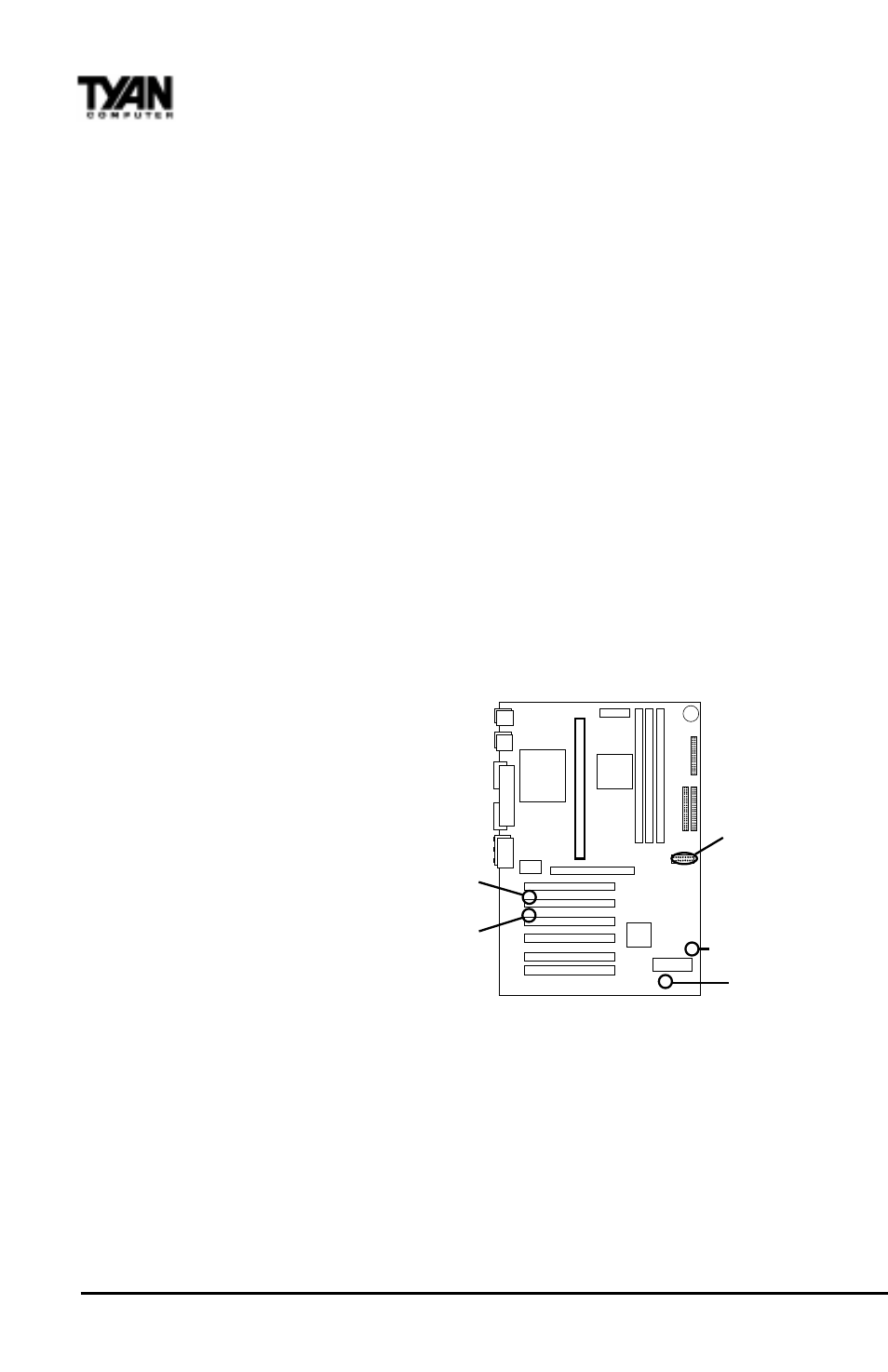
CON3
(WOL)
J16
J12 (Speaker)
CON2
(WOR)
JP2(Clr CMOS)