Display, 2 − features of the cd-rw901 – Teac CD-RW901 User Manual
Page 12
1
TASCAM CD-RW901
Display
!
S D F
G
HJ
#
^
&
*
( )
W
T
Y
U
I
O
P
Q
$
@
A
%
E
R
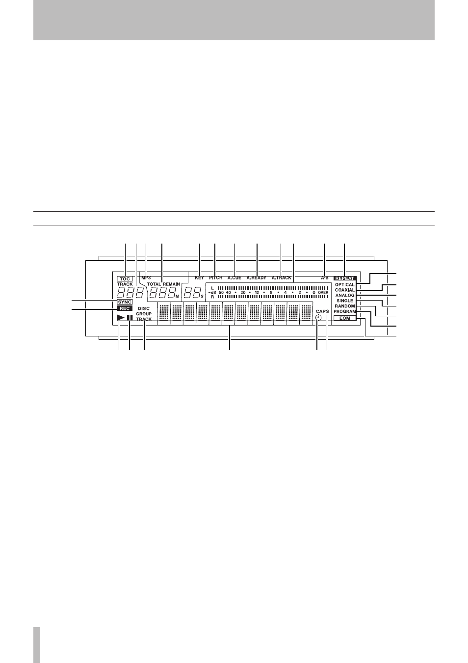
This display shows various types of operation informa-
tion, including CD disc information, deck operation
modes, and menu status.
!
TOC
The
TOC
indicator lights up red when a loaded
disc contains
TOC (Table of Contents) data.
@
Track number display
During playback or selec-
tion, the track number is displayed.
When Incremental playback is on, and when in play-
back or playback ready mode, the
TRACK
indicator
blinks.
#
MP3
The
MP3
indicator lights when a MP3 disc is in
the deck.
$
Counter display
Depending on the time display
mode,
TOTAL
or
REMAIN
are lit. The counter display
indication are in minutes (three digits) and seconds
(two digits).
%
KEY
The
KEY
indicator lights when Key Control is
on.
^
PITCH
The
PITCH
indicator lights when Pitch
Control is on.
&
A.CUE
The
A.CUE
indicator lights when Auto Cue is
on.
*
A.READY
The
A.READY
indicator lights when Auto
Ready is on.
(
A. TRACK
The
A.TRACK
indicator
lights when the Auto
Track is on.
)
Meter
This displays the playback level, as well as
the input level of the source device.
Q
A-B
The
A-B
indicator lights when the A-B repeat
function is on.
Also, this flashes until a “B-point” is entered.
W
REPEAT
The
REPEAT
indicator lights when the
Repeat function is on.
E
SYNC
The
SYNC
indicator lights up when SYNC is
on.
R
REC
When the SRC function is on, this lights dur-
ing recording, or in recording standby mode.
When the SRC function is off, this flashes during
recording, or in recording standby mode.
b
ATT control right and left
Use a small Phillips
screwdriver with these attenuators to reduce the out-
put level from either the right or left balanced analog
output. The adjustable level is up to -10 dB.
n
ANALOG OUT (BALANCED) (L, R)
These XLR
connectors output analog audio signals at +4 dBu to
suitably-equipped units.
The wirings are: 1=grounding, 2=hot, 3=cold.
m
CONTROL I/O (parallel) terminal
Use this 15-pin
D-sub connector to connect the unit to suitably-
equipped units, allowing control of the CD-RW901.
The pinouts of this connector are described (see
Connections” on page 9).
,
CONTROL I/O (RS-232C) terminal
RS-232C com-
patible serial control from an external PC can be
performed.
.
REMOTE IN terminal
Connects the supplied
RC-RW901 remote control unit.
/
AC IN jack
Connects the power cable supplied.
2 − Features of the CD-RW901