On. table 2.1, Figure 2.1) a – Telex MCE325 User Manual
Page 22
2-2
C S I - 2 0 0 U s e r I n s t r u c t i o n s
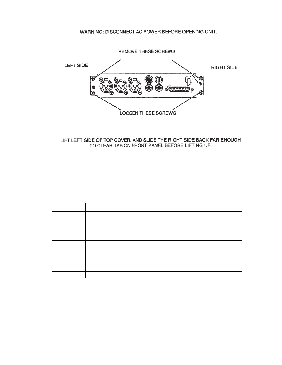
Figure 2.1
Top cover removal.
Intercom Line-Channel Configurations (DS1-DS3, J6, J7, J19 & J20)
The four channels of the MCE325 may be assigned to intercom lines in a variety of ways.
Channel assignment is determined by the settings of DIP switches DS1 through DS3 and jumpers
J6, J7, J19, and J20. There are six possible intercom line configurations. These are listed in Table
2.3 together with the proper DIP switch and jumper settings for each.
NOTE
The terms “two-channel mode” and “four-channel mode” apply only to two-wire lines. In two-
channel mode, each two-wire line uses two channel selector buttons: one for talk and one for
listen. In four-channel mode, each two-wire line uses one channel selector button for both talk and
listen.
The two-channel mode should be selected under only two circumstances:
1
When only one or two two-wire lines are connected to channels one and two only.
Table 2.1
DIP switch functions and default settings.
Switch Number Switch Function
Default Setting
DS1
four-wire CH A output not installed (off), four-wire CH A output installed
(on)
Off
DS2
four-wire CH B output not installed (off), four-wire CH B output installed
(on)
Off
DS3
two-channel mode (off)*, four-channel mode (on)
Off
DS4
Front panel setup lock-out disabled (off), Front panel setup lock-out
enabled (on)
Off
DS5
Listen and talk muted during ISO (off), Talk only muted during ISO (on) Off
DS6
Not used
Off
DS7
Talk-off transmit disabled (off), Talk-off transmit enabled (on)
On
DS8
VOX disabled (off), VOX enabled (on)
Off