Installation, Set the 4-position switch, Set the jumper – Transition Networks CETTF10XX-200 User Manual
Page 2: Continued install the slide-in-module, Connect the twisted-pair copper cable, Lks pwr lkm lks pwr lkm, Term init rx tx lnk pwr
CETTF10xx-200
2
24-hour Technical Support: 1-800-260-1312 -- International: 00-1-952-941-7600
Installation
CAUTION: Wear a grounding device and observe electrostatic discharge
precautions when setting the 4-position switch and the jumper. Failure to
observe this caution could result in damage to, and subsequent failure of, the
media converter.
Set the 4-Position Switch
•
The 4-position switch is
located on the media
converter circuit board.
•
Use a small flat-blade
screwdriver to set the
switches (see the drawing).
NOTE: When the fiber port or the copper port is disabled (switches 1 and 2),
network traffic coming into the media converter is ignored and no traffic flows
out. In this mode, the media converter is disconnected from the network.
1.
Fiber Port (10Base-FL)
Up
Enables network traffic on the fiber port.
Down
Disables network traffic on the fiber port.
2.
Copper Port (10Base-T)
Up
Enables network traffic on the copper port.
Down
Disables network traffic on the copper port.
3.
AutoCross
Up
Enables AutoCross (see page 6).
Down
Disables AutoCross.
(When AutoCross is disabled, the 10Base-T (copper) port is in
MDI-X (crossover) mode.)
4.
Link Pass-Through
Up
Enables Link Pass-Through (see page 6).
Down
Disables Link Pass-Through.
(When Link Pass-Through is disabled, remote faults are not
passed along to any downstream equipment.)
Set the Jumper
The jumper is located on the media converter circuit board. Use small
needle-nosed pliers or a similar device to set the jumper.
Hardware
The media converter mode is determined
by the 4-position switch settings.
Software
The media converter mode is determined
by the most-recently saved, on-board
microprocessor settings.
Software Mode
Hardware Mode
H
S
H
S
Fiber Port; Up=On
Copper Port; Up=On
Link Pass Through; Up=On
AutoCross™; Up=On
1 2 3 4
3
[email protected] -- Click the “Transition Now” link for a live Web chat.
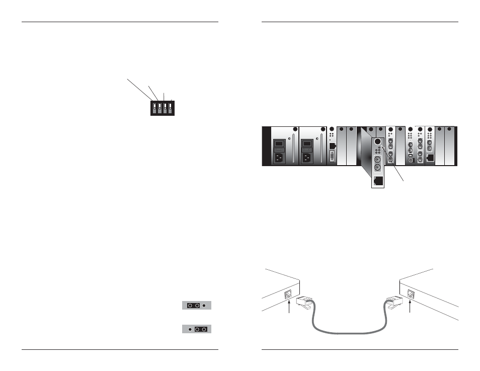
Installation
-- Continued
Install the Slide-in-Module
CAUTION: Wear a grounding device and observe electrostatic discharge
precautions when installing the CETTF10xx-200 slide-in-module media
converter. Failure to observe this caution could result in damage to, and
subsequent failure of, the media converter.
To install the CETTF10xx-200 slide-in-module media converter.
1.
Carefully slide the slide-in-module into the installation slot, aligning the
module with the installation guides.
2.
Ensure that the module is firmly seated inside the chassis.
3.
Push in and rotate the attached panel fastener screw clockwise to secure
the module to the chassis front.
Connect the Twisted-Pair Copper Cable
1.
Locate or build IEEE 803.2
™
compliant 10Base-T cables, with straight-
through RJ-45 cable, and with straight-through RJ-45 connectors installed
at both ends.
2.
Connect the RJ-45 connector at one end of the cable to the RJ-45 port on
the CETTF10xx-200 media converter.
3.
Connect the RJ-45 connector at the other end of the cable to the RJ-45
port on the other device (switch, workstation, etc.).
CFMFF100
CFMFF100
CETCF100
CFETF100
CFETF110
CFMFF100
SPD
PWR
FRX
CRX
FLNK
CLNK
10/100TX
RX
TX
10/100SX
100BASE-TX
RX
TX
100BASE-FX
Link Alert
E
D
0
50½
LA
PWR
RXF
RXC
COL
LKS
PWR
LKM
10BASE-2
10BASE-FL
LKS
PWR
LKM
LKS
PWR
LKM
Multimode
Singlemode
TX
RX
TX
RX
Multimode
Singlemode
TX
RX
TX
RX
Multimode
Singlemode
TX
RX
TX
RX
I
0
TERM
INIT
RX
TX
LNK
PWR
CPSMM120
SERIAL
10BASE-T
R
E
S
E
T
I
0
RX
TX
Panel Fastener Screw
PWR
RXF
LKF
RXC
LKC
RJ-45 port
on the other device
(switch, work station, etc.)
RJ-45 port
on the media
converter