Installation, Set the 4-position switch, Continued set the jumpers – Transition Networks CBFTF10XX-15X User Manual
Page 2: Installing the slide-in-module, 050½ link alert e d, Lks pwr lkm lks pwr lkm, Term init rx tx lnk pwr
2
CBFTF10xx-15x
Tech Support: 800-260-1312 International: 952-941-7600 7am-6pm CST (GMT-6:00)
INSTALLATION
CAUTION: Wear a grounding device and observe electrostatic discharge
precautions when setting the 4-position switch and the jumper(s) and when
installing the Slide-in-Module. Failure to observe this caution could result in
damage to, and subsequent failure of, the Media Converter.
Set the 4-Position Switch
The 4-position switch is located on the
side of the Media Converter. Use a
small flatblade screwdriver or a similar
device to set the recessed switches.
Refer to the drawing for the locations
of the four individual switches.
1. Auto-Negotiation
UP
Enables Auto-Negotiation on the copper port.
Advertises 100 Mb/s full-duplex and half duplex,
and 10 Mb/s full-duplex and half duplex.
DOWN
Disables Auto-Negotiation on the copper port.
2. Copper Mode
(Applies only if switch 1 is DOWN.)
UP
Forces full-duplex operation on the copper port.
DOWN
Forces half-duplex operation on the copper port.
3. Speed
(Applies only if switch 1 is DOWN.)
UP
Forces 100 Mb/s operation on the copper port.
DOWN
Forces 10 Mb/s operation on the copper port.
4. Fiber Mode
UP
Forces full-duplex operation on the fiber port.
DOWN
Forces half-duplex operation on the fiber port.
Speed (UP=100Mb/s)
Copper Mode (UP=Full-Duplex)
Auto-Negotiation (UP=Enabled)
Fiber Mode
(UP=Full-Duplex)
1 2 3 4
[email protected] -- Select the “Transition Now” Link for a Live Web Chat
3
INSTALLATION
-- Continued
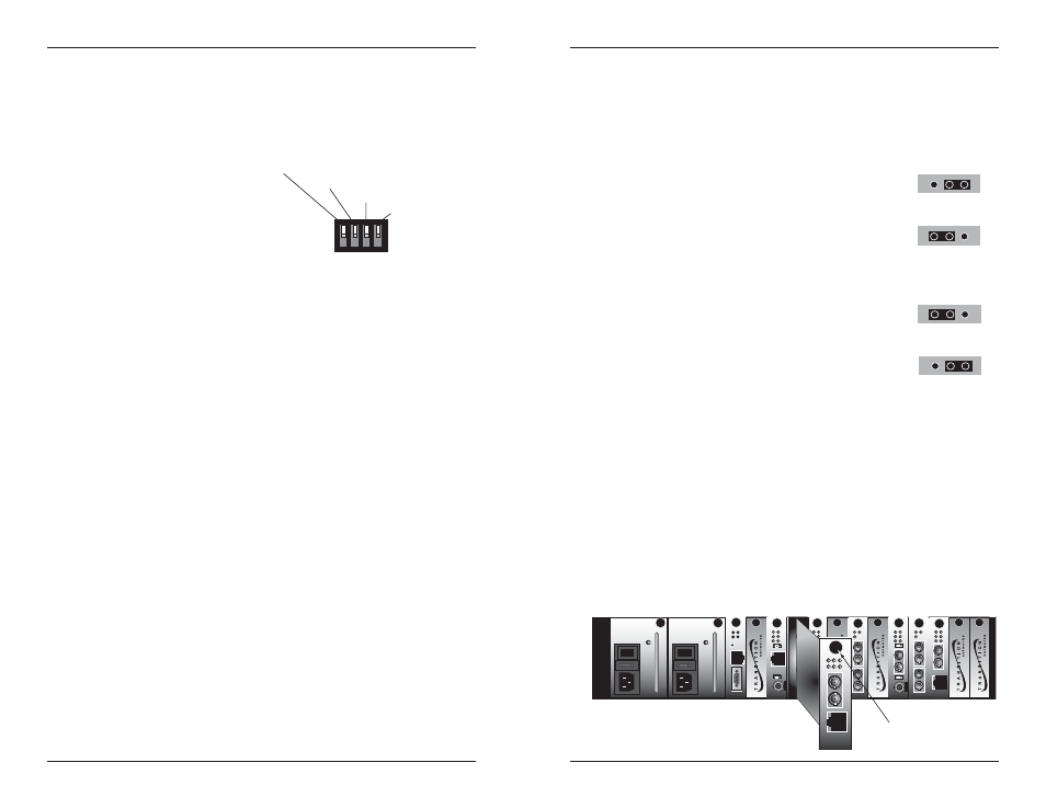
Set the Jumpers
The jumpers are located on the Media Converter circuit board. Use small
needle-nosed pliers or a similar device to set the jumper.
The Hardware/Software jumper is labeled “H” for hardware and “S” for
software (see the drawing below).
Hardware The Media Converter mode is determined by
the 4-position switch settings listed above.
Software
The Media Converter mode is determined by
the most-recently saved, on-board
microprocessor settings.
The Far-End Fault jumper is labeled “FE” for enable Far-End Fault and “FD”
for disable Far-End Fault (see the drawing below).
Enable
A fault on the fiber link causes the Media
Converter to transmit a Far-End Fault signal.
Disable
No Far-End Fault signal is transmitted when a
fault occurs.
Software Mode
Hardware Mode
S
H
S
H
Disable Far-End Fault
Enable Far-End Fault
FE
FD
FE
FD
Installing the Slide-In-Module
CAUTION: Slots in the PointSystem™ Chassis without a Slide-in-Module
installed MUST have a protective plate covering the empty slot for Class A
and/or Class B compliance.
To install the CGETF10xx-15x Media Converter Slide-in-Module:
1.
Locate an empty installation slot on the PointSystem™ Chassis.
2.
Carefully slide the Slide-in-Module into the installation slot, aligning the
Slide-in-Module with the installation guides.
3.
Ensure that the Slide-in-Module is firmly seated against the back of the
chassis.
4.
Secure the Slide-in-Module by securing the panel fastener screw
(attached to the Slide-in-Module) to the chassis front.
CFMFF100
10BASE-2
CECF100
CFMFF100
0
50½
Link Alert
E
D
CETCF100
CFETF100
CFETF110
CFMFF100
LA
PWR
RXF
RXC
LNK
COL
SPD
PWR
FRX
CRX
FLNK
CLNK
SPD
PWR
FRX
CRX
FLNK
CLNK
10/100TX
RX
TX
10/100SX
100BASE-TX
RX
TX
100BASE-FX
Link Alert
E
D
0
50½
LA
PWR
RXF
RXC
LNK
COL
LKS
PWR
LKM
10BASE-2
10BASE-FL
10BASE-T
LKS
PWR
LKM
LKS
PWR
LKM
Multimode
Singlemode
TX
RX
TX
RX
Multimode
Singlemode
TX
RX
TX
RX
Multimode
Singlemode
TX
RX
TX
RX
I
0
TERM
INIT
RX
TX
LNK
PWR
CPSMM120
SERIAL
10BASE-T
R
E
S
E
T
I
0
Panel Fastener Screw