Tyan Computer Tank GT25 B5381 User Manual
Page 60
52
Chapter 3: Replacing Pre-Installed Components
3.7.2 System Fan Layout
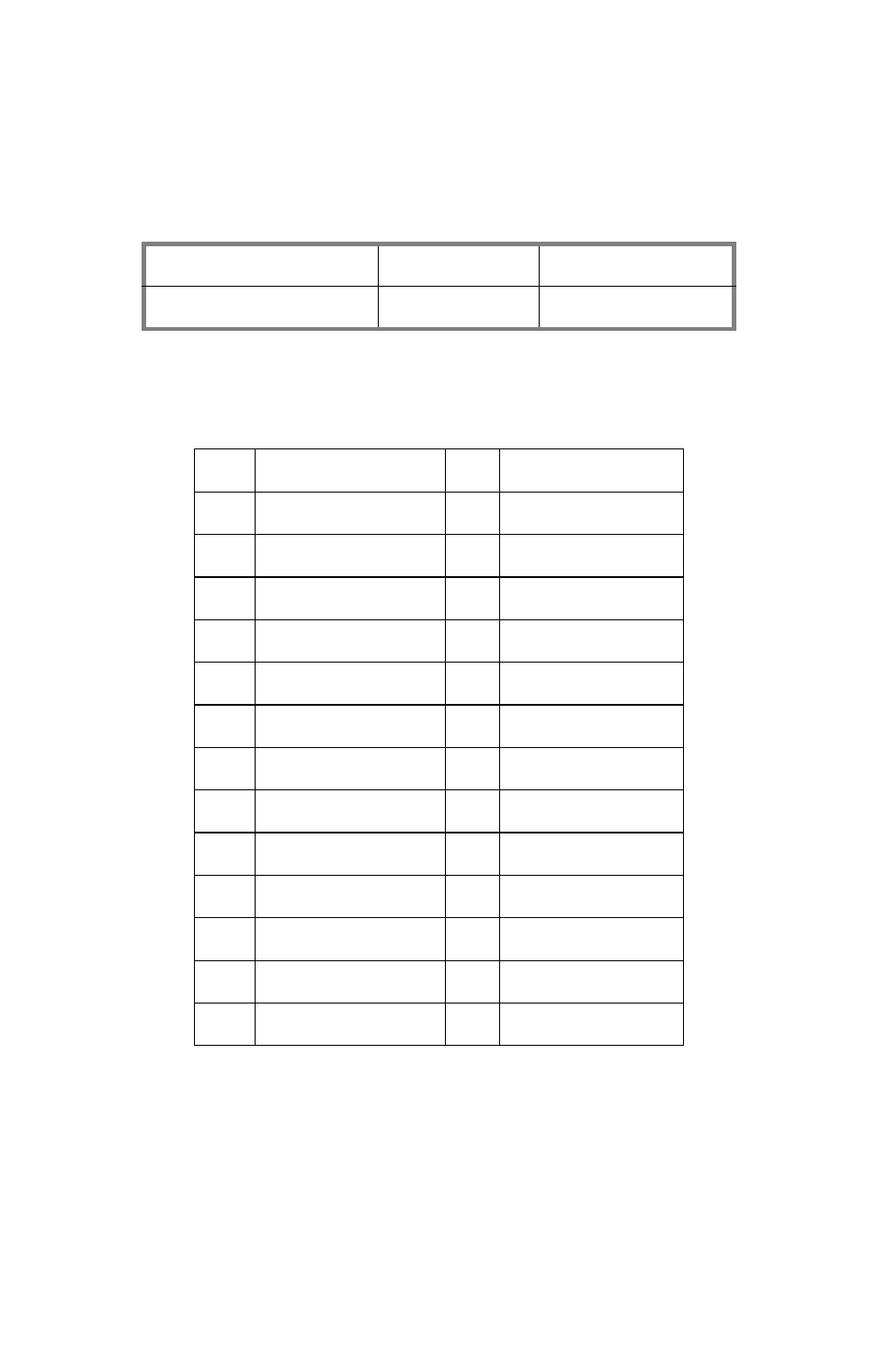
The following table provides the information for system fan
layout.
System Fan Speed Control Signal
3.7.3 M1210 Adapter Board Connector Pin Definitions
J14 Front Panel Connector
M1210 Adapter Board
Connect to
Motherboard
J16 (PWM Signal)
Æ
J11 (PWM Signal)
1
HDLED+
2
HDLED-
3
RESET+
4
RESET-
5
PW_LED+
6
PW_LED-
7
WLED+
8
WLED -
9
ICH_SMBDAT
10
ICH_SMSCLK
11
EXT_INT
12
VOLTAGE5
13
NC
14
INTRU#
15
PWR_SW+
16
PWR_SW-
17
LAN1_LED+
18
LAN1_LED -
19
LAN2_LED+
20
LAN2_LED-
21
NC
22
NC
23
ID_LED+
24
ID_LED-
25
ID_SW+
26
ID_SW-
27
KEY PIN
28
NC