2. white peak bending correction circuit – Toshiba TW40F80 User Manual
Page 72
72
4-2. White Peak Bending Correction Circuit
4-2-1. Outline
White peak area in screen picture may sometimes cause bend-
ing in picture. See figure below.
In TP48E60 series, correction signal which video ripple in
video output circuit power supply 200V is input to pin 24
(Bending correction terminal) of Q501. This corrects white
peak bending.
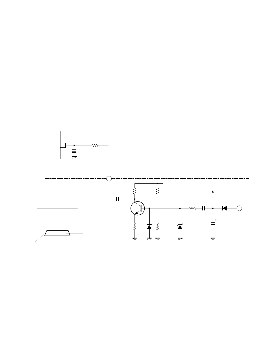
4-2-2. Operation Theory
Fig. 9-11 shows circuit diagram. Video ripple in video out-
put circuit power supply 200V suffers DC cut by C475, and
is inverted in Q470, then input to pin 24 of Q501 via C481.
Pin 24 of Q501 is a bending correction terminal. The volt-
age which is applied to this terminal, controls phase of video
signal to correct white peak bending.
Q501
24
Bending correction
terminal
EHT
C415
93
Receiving Board
Power, Def board
BB91
C481 Inversion
Q470
R481
R482
D470
R483
R484
D474
R478
C475
C466
D406
200V
9V
White peak
Bending by white peak
T416
3
R379
Fig. 9-11 White peak bending correction circuit
- 65NH84 (68 pages)
- TXP451 (9 pages)
- 46H84 (64 pages)
- 57HM117 (74 pages)
- TLP511U (47 pages)
- 62HM195 (112 pages)
- TDP-D2 (20 pages)
- TDP-T90 (25 pages)
- TP 50H60 (63 pages)
- 72MX195 (136 pages)
- T620 (37 pages)
- Camileo TDP-S20 (25 pages)
- 62HM84 (68 pages)
- Data TDP-T420 (29 pages)
- 43H72 (56 pages)
- 53AX62 (2 pages)
- TXP650 (52 pages)
- MP8640 (30 pages)
- PROJECTORS (8 pages)
- TLP260 (78 pages)
- TLP780E (80 pages)
- DLP 46HM95 (112 pages)
- TLF-XD2000 (28 pages)
- TDP-T100 (28 pages)
- TLP-B2U (67 pages)
- 56HM66 (56 pages)
- TLP 261 (2 pages)
- MP8745 (39 pages)
- Integrated High Definition DLP Projection Televison 62HM196 (92 pages)
- TDP-TW90A (37 pages)
- 57HX94 (2 pages)
- COLORSTREAM SRS TOUCHFOCUS 57H84C (64 pages)
- TDP-S9 (43 pages)
- TDP-T91 (25 pages)
- t90 (2 pages)
- TDP-P75 (45 pages)
- T501U Series (2 pages)
- TDP-T90U (2 pages)
- TDP-TW420U (1 page)
- TDP-TW300 (1 page)
- P503DL (41 pages)
- TDP-TW90 (37 pages)
- G 3 (2 pages)
- 51H93 (100 pages)
- Projector-Laptop (5 pages)