Section iv: dvd switch circuit, Dvd switch block diagram, Outline – Toshiba TW40F80 User Manual
Page 35
35
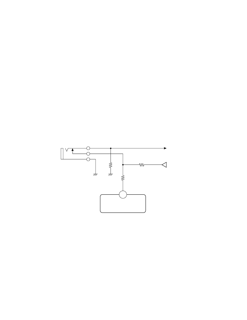
2. OUTLINE
In this model, the DVD input terminals are provided in or-
der to receive the color difference signals (Y, Cr, Cb) out-
put from a DVD player.
The luminance (Y) signal input for DVD input uses the
VIDEO input terminal in common with the VIDEO 2 input.
The terminals for color difference signal inputs Cr (R – Y)
and Cb (B – Y) are used exclusively.
The input identification for VIDEO 2 and DVD is carried
out by setting pin 21 of QV01 TA1218N (AV SW IC) from
“L” to “H” when the cable is connected to the Cb input ter-
minal with a switch equipped.
The main microprocessor QA01 sets pin 10 of QA01 from
“L” to “H” through I
2
C bus when pin 21 of AW SW IC
develops “H”.
Cb input
Open : at Cb input
RV26
75
RV27
10k
RV28 100k
+9v
Cb to DVD SW unit
21
QV01 TA1218N
Fig. 4-2
- 65NH84 (68 pages)
- TXP451 (9 pages)
- 46H84 (64 pages)
- 57HM117 (74 pages)
- TLP511U (47 pages)
- 62HM195 (112 pages)
- TDP-D2 (20 pages)
- TDP-T90 (25 pages)
- TP 50H60 (63 pages)
- 72MX195 (136 pages)
- T620 (37 pages)
- Camileo TDP-S20 (25 pages)
- 62HM84 (68 pages)
- Data TDP-T420 (29 pages)
- 43H72 (56 pages)
- 53AX62 (2 pages)
- TXP650 (52 pages)
- MP8640 (30 pages)
- PROJECTORS (8 pages)
- TLP260 (78 pages)
- TLP780E (80 pages)
- DLP 46HM95 (112 pages)
- TLF-XD2000 (28 pages)
- TDP-T100 (28 pages)
- TLP-B2U (67 pages)
- 56HM66 (56 pages)
- TLP 261 (2 pages)
- MP8745 (39 pages)
- Integrated High Definition DLP Projection Televison 62HM196 (92 pages)
- TDP-TW90A (37 pages)
- 57HX94 (2 pages)
- COLORSTREAM SRS TOUCHFOCUS 57H84C (64 pages)
- TDP-S9 (43 pages)
- TDP-T91 (25 pages)
- t90 (2 pages)
- TDP-P75 (45 pages)
- T501U Series (2 pages)
- TDP-T90U (2 pages)
- TDP-TW420U (1 page)
- TDP-TW300 (1 page)
- P503DL (41 pages)
- TDP-TW90 (37 pages)
- G 3 (2 pages)
- 51H93 (100 pages)
- Projector-Laptop (5 pages)