Switched pdus, Pdu power cycle, Pdu on off – Tripp Lite 200803016 95-2924 User Manual
Page 6: Specifications, Aload shedding remote reboot, Remote outlet control applications b
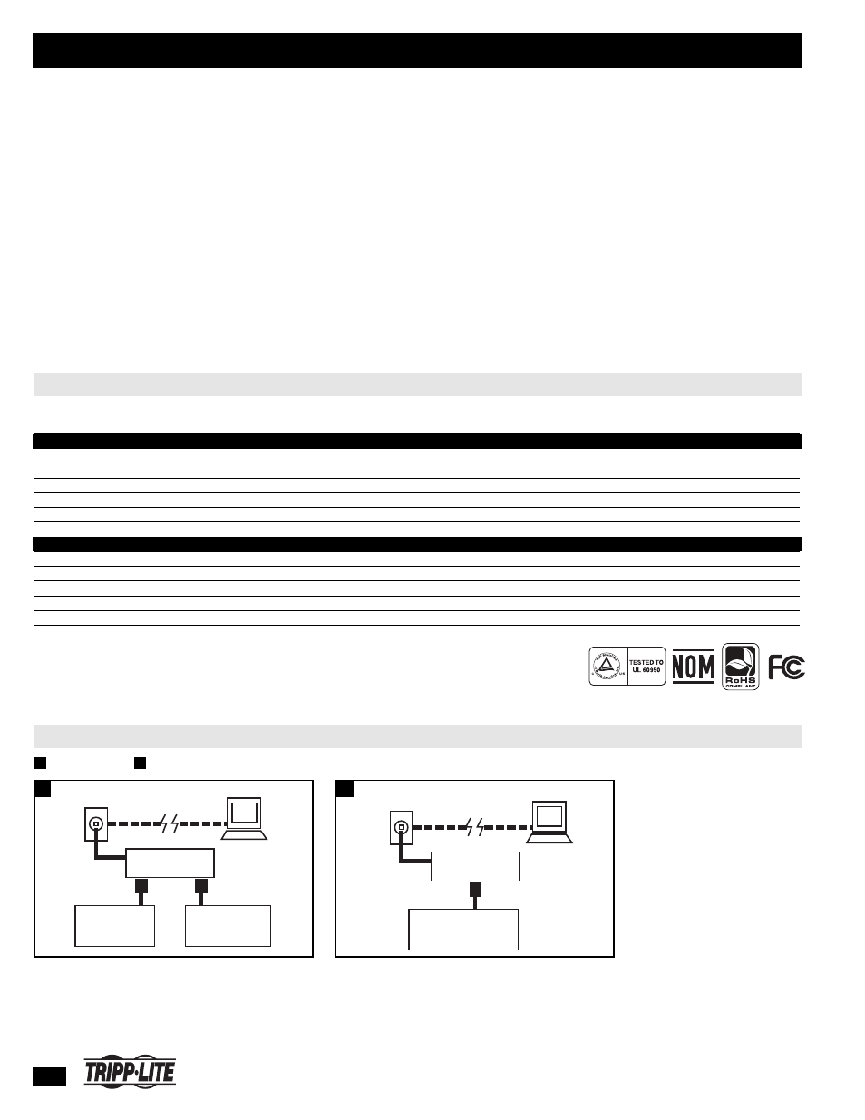
PDU
Power Cycle
Network Jack
TCP/IP
Remote Computer
LOCKED/FROZEN
DEVICE
6
Tripp Lite World Headquarters 1111 W. 35th Street, Chicago, IL 60609 USA • (773) 869-1234 • www.tripplite.com
Switched PDUs
Tripp Lite Switched PDUs reliably distribute AC power from a UPS system, generator or utility wall outlet to multiple devices. A built-in network
interface allows users to remotely control individual outlets (and connected devices) via SNMP, Web or Telnet. This feature reduces the frequency of
costly service calls by enabling remote reboot of locked devices. It can also be used to extend the runtime of critical devices by allowing users to
turn off nonessential devices during a blackout. Each model features one or more digital load meters that help you maximize the amount of devices
that can be safely added to the PDU (without overloading it) by displaying the total power consumption of connected equipment. High-quality
plug/outlet connections and a switch-free design prevent the PDU from being accidentally disconnected or shut down. Versatile all-metal cabinets
with detachable mounting hardware accommodate a variety of mounting options: wallmount, under-counter and 19-inch rackmount mounting in 1U
and/or zero-U formats*. Switched PDUs are available in 15A, 20A and 30A capacities.
* See specifications for mounting options supported by each model.
✔ Remote Control of Individual Outlets
✔ Remote Monitoring and Condition Reporting
✔ Digital Load Meter(s)
✔ Multiple Outlets
✔ Long Input Power Cord
✔ All-Metal Cabinet with
Versatile Mounting Options
Input
Unit
0U
Wallmount/
Input
Maximum
Plug
Outlet
Input Cord
Dimensions
1U or 2U
Vertical Under Counter
Model
Voltage
Input Current
Meters
Type
Qty. & Type
(E)
Length
(H x W x D, in)
Rackmount
Mount
Mount
Horizontal Models
PDUMH15ATNET
120V
(A)
15A
1 x 15A
5-15P
8 (5-15R)
2 x 12 ft.
1.75 x 17.5 x 14.5
1U
✔
✔
PDUMH20ATNET
120V
(A)
20A
1 x 20A
L5-20P / 5-20P
(D)
16 (5-15/20R)
2 x 12 ft.
1.75 x 17.5 x 14.5
1U
✔
✔
PDUMH30NET
120V
30A
(B)
1 (2 x 20A)
(C)
L5-30P
16 (5-15/20R)
10 ft.
3.5 x 17.5 x 12.5
2U
✔
✔
PDUMH15HVNET
208/230V
15A
(B)
1 x 15A
C14 inlet
8 (C13)
6.5 ft.
1.75 x 17.5 x 14.75
1U
✔
✔
PDUMH20HVNET
208/230V
20A
(B)
1 x 20A
L6-20P (C20 inlet)
8 (C13)
8.5 ft.
1.75 x 17.5 x 14.75
1U
✔
✔
PDUMH30HVNET
208V
30A
(B)
1 (2 x 15A)
(C)
L6-30P
16 (C13)
10 ft.
3.5 x 17.5 x 12.5
2U
✔
✔
Vertical Models
PDUMV15NET
120V
15A
(B)
1 x 15A
5-15P
16 (5-15/20R)
10 ft.
4.25 x 49 x 2.25
n/a
✔
✔
PDUMV20NET
120V
20A
(B)
1 x 20A
L5-20P / 5-20P
(D)
24 (5-15/20R)
10 ft.
4.25 x 63 x 2.25
n/a
✔
✔
PDUMV30NET
120V
30A
(B)
1 (2 x 20A)
(C)
L5-30P
24 (5-15/20R)
10 ft.
4.25 x 70 x 2.25
n/a
✔
✔
PDUMV20HVNET
208/230V
20A
(B)
1 x 20A
L6-20P (C20 inlet)
24 (20 C13 / 4 C19)
10 ft.
4.75 x 64 x 2.25
n/a
✔
✔
PDUMV30HVNET
208V
30A
(B)
1 (2 x 15A)
(C)
L6-30P
24 (20 C13 / 4 C19)
10 ft.
4.75 x 70 x 2.25
n/a
✔
✔
(A)
Primary input (fixed cord) tolerances: 99-138V, 45-65Hz. Outside of this range, the PDU switches to the secondary input (detachable cord) if within 99-138V range. Two front panel LEDs marked “primary” and
“secondary” indicate the active input source. Includes built-in Ethernet jack with programmed and real-time remote control options via SNMP, Web or Telnet.
(B)
Code-derated maximum input current is 80% of value shown.
(C)
Switchable meter displays total load for PDU or for each output bank.
(D)
Includes twist-lock input plug(s) and adapter(s) to support connection to a straight-blade outlet.
(E)
5-15/20R outlets accept 5-15P or 5-20P plugs.
SPECIFICATIONS
TCP/IP
PDU
ON
OFF
Network Jack
Remote Computer
CRITICAL
LOAD
NON-CRITICAL
LOAD
A
Load Shedding
Remote Reboot
B
A
REMOTE OUTLET CONTROL APPLICATIONS
B
Certifications vary by model.