Installation, Networking the pdu, Dynamic ip address assignment – Tripp Lite Switched Rack PDU User Manual
Page 4: Static ip address assignment
4
Installation
continued
Networking the PDU
Note: The MAC address of the PDU (a 12-digit string in this format: 000667xxxxxx) is printed on a label attached to the PDU
enclosure. The MAC address is also printed on a label attached to the internal network card.
If your network's DHCP server will assign a dynamic IP address to the PDU automatically, go to Step
.
If you will assign a static IP address to the PDU manually, go to Step
. If you are uncertain which method
to use, contact your network administrator for assistance before continuing the installation process.
Dynamic IP Address Assignment
3-1
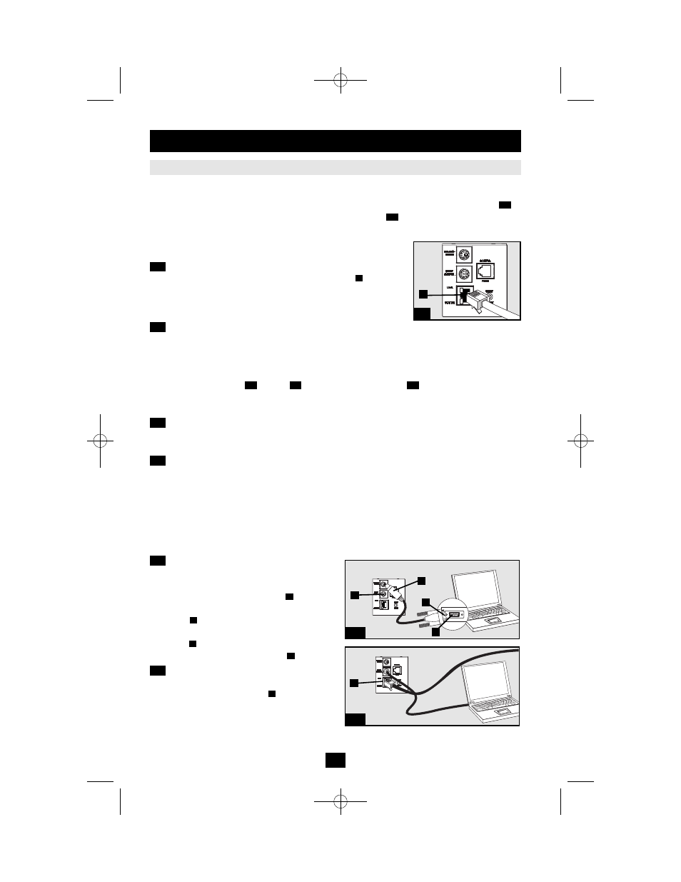
Connect PDU to Network: While the PDU is powered, connect a
standard Ethernet patch cable to the RJ-45 Ethernet port
on the PDU.
Note: This port is not compatible with PoE (Power over Ethernet) applications.
The PDU will attempt to obtain an IP address via DHCP. This may take
as long as several minutes, depending on your network environment.
3-2
Discover IP Address: Contact your network administrator to determine which dynamic IP
address has been assigned to the PDU by the DHCP server. The PDU can be identified on the DHCP
server by referring to its MAC address. (The MAC address is a 12-digit string in this format:
000667xxxxxx. Refer to the MAC address label attached to the PDU.) You may wish to request a
long-term lease period for the IP address, depending on your application. After you have discovered
the IP address, skip Steps
through
and proceed directly to Step
.
Static IP Address Assignment
4-1
Determine IP Information: Before assigning a static IP address, you'll need to know the IP
address, gateway address and subnet mask. If you do not have this information, contact your network
administrator for assistance.
4-2
Configure Terminal Emulation Program: Open a VT100-compatible terminal emulation
program (such as the HyperTerminal program bundled with Microsoft
®
Windows
®
) on a computer
with an available DB9 serial port. (A notebook computer may be the most convenient choice.) Set the
terminal emulation program to use the COM port that corresponds to the computer’s DB9 serial port.
Specify the parameters required to communicate with the PDU terminal interface:
If the terminal emulation program supports multiple emulation modes, you may also need to specify VT100 emulation.
4-3
Connect PDU to Computer: Use the mini-
DIN to DB9 serial cable (part number 73-1025)
included with the PDU to connect the PDU to
the computer. The circular connector
at one
end of the cable attaches to the 8-pin mini-DIN
serial port
on the PDU. (Align the connector
carefully to avoid damaging the pins.) The DB9
connector
at the other end of the cable
connects to the computer's serial port .
4-4
Connect PDU to Network: While the PDU
is powered, connect a standard Ethernet patch
cable to the RJ-45 Ethernet port
on the PDU.
Note: This port is not compatible with PoE (Power over
Ethernet) applications.
A
D
C
B
A
5-1
4-6
4-1
A
4-1
3-1
3-1
A
Bits per second:
9600
Data bits:
8
Parity:
None
Stop bits:
1
Flow control:
None
4-3
4-4
A
B
C
D
A
200801103 93-2721 Switched PDU OM.qxd 1/24/2008 2:58 PM Page 4