Chapter 4 operation – TDK 500A User Manual
Page 21
83-493-001 Rev. K
13
CHAPTER 4 OPERATION
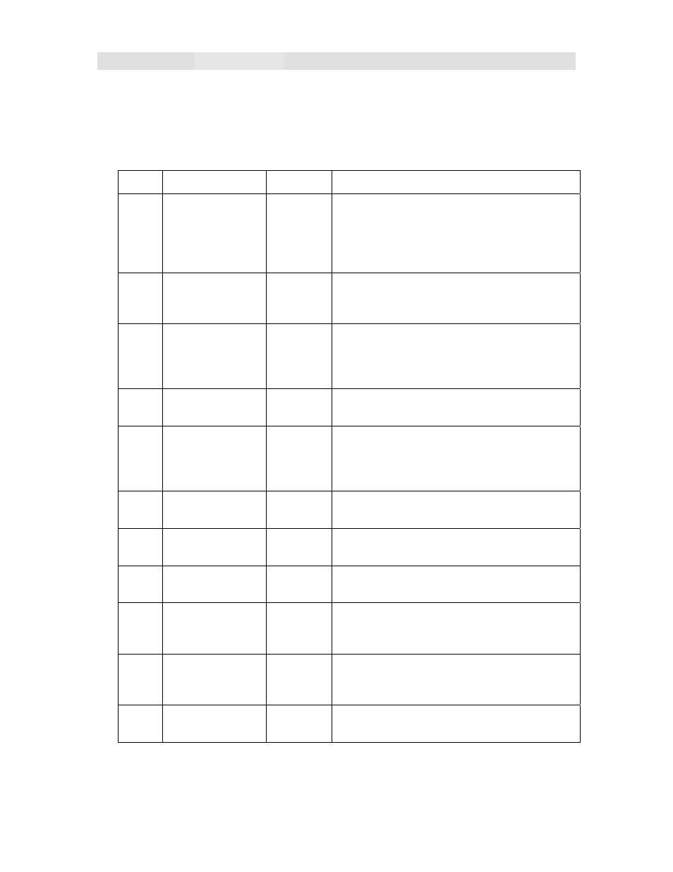
4.1 REMOTE CONTROL
The Series 500A/102A/152A/202A is easily controlled through the remote connector on
the input panel of the unit. Only the ENABLE/RESET, V PROGRAM and GND signals
are required for operation. The remaining signals are provided for status monitoring and
fault diagnosis. A schematic diagram showing the suggested interface circuit is shown in
Figure 4-1. This table is for a standard configuration.
PIN SIGNAL
NAME I/O
DESCRIPTION
1
ENABLE/RESET INPUT
A high signal (+10 to 15V) with respect to
ground (pin 14) will enable the power
supply. Latching faults can be cleared by
cycling this switch. Ground or open disables
the supply.
5
V PROGRAM
INPUT
A 0-10V signal with respect to ground at
this pin programs the output voltage
proportionally form zero to rated output.
7
VPEAK
OUTPUT A 0-10V signal with respect to ground
proportional to the peak of the output
charging voltage. Can be used to drive a
meter displaying peak output voltage.
8
V ANALOG
OUTPUT 0-10V analog of output charging voltage
waveform.
10
INHIBIT
INPUT
A +10 TO 15V with respect to ground,
disables the unit. Open or ground allows
operation. This input can be used to disable
charging during HV switch recovery.
9,
11 +15V
OUTPUT 15V regulated. Can be used or user
programming applications 20mA max.
14
GND
OUTPUT Control circuit return. Also chassis/earth
ground
15
INHIBIT LED
OUTPUT Open collector. Indicates that the power
supply is receiving an INHIBIT signal.
13
EOC LED
OUTPUT Open collector. Indicates that the power
supply is reaching end-of-charge, i.e. the V
PROGRAM set point.
3, 6
SUMMARY
FAULT LED
OUTPUT Open collector. Indicates an output
overvoltage. Temperature fault or low input
voltage condition.
2
LOAD FAULT
OUTPUT Indicates a shorted O/P or a very large load
capacitor.
Table 4-1 Control Interface Connection for Standard 500A/102A/152A/202A Series