Step 7: backguard installation – Thermador PRDS304 User Manual
Page 22
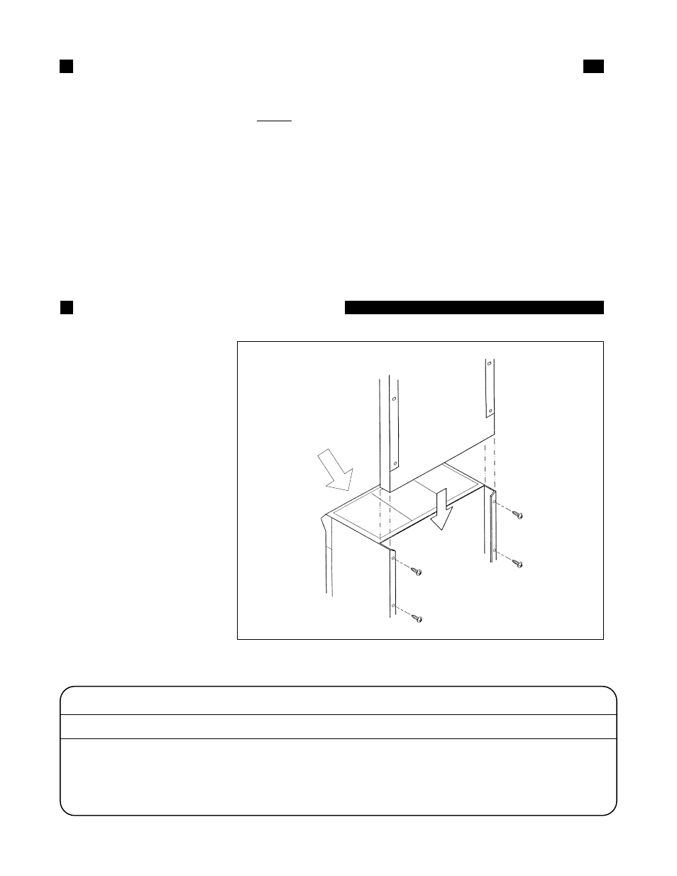
Chart D: BACKGUARD KIT MODEL NUMBERS
RANGE MODEL NO.
9" STD. LOW BACK
12" LOW BACK
22" HIGH SHELF
1-1/2" ISLAND TRIM
PRDS304/PRG304
Included with Range
N/A
PHS30T
PRS30ITS
PRDS36/PRG36
N/A
PRS36LBS
PHS36T
PRS36ITS
PRDS48/PRG48
N/A
PRS48LBS
PHS48T
PRS48ITS
FIG. 22
Front of Unit
STEP 6: ELECTRICAL REQUIREMENTS, CONNECTIONS & GROUNDING
CASE 2: Electrical Connections and Grounding
with a 4-Conductor Power Supply (to be
used only when local codes do not per-
mit grounding through the neutral).
Secure the neutral (white) wire of the supply
circuit to the neutral terminal of the NEMA
14-50R receptacle. Connect the L1 (black)
and the L2 (red) hot leads to the other termi-
nals on the NEMA 14-50R receptacle. Con-
nect a separate ground (green) wire to the
grounding terminal of the NEMA 14-50R
receptacle.
If range is hard-wired to power supply, follow
the instructions for permanent connection on
pages 17 and 18. The ground wire must be
brought out to the junction box on the
range and connected to the box, per the
instructions.
Ensure that the house supply wires and
all electrical connections meet require-
ments of all applicable codes.
DO NOT GROUND TO A GAS SUPPLY PIPE.
Improper grounding will cause malfunction (such
as continuous sparking of the burner igniters),
may damage this appliance, and could create a
condition of shock hazard at the igniter of each
burner. It is the responsibility and obligation of
the installer or user to ensure that the appliance
is properly grounded.
The backguard must be attached
before sliding the range into the
final installed position. A Low Back
or High Shelf backguard must be
installed when there is less than a
12" clearance between combustibles
and the back of the range above
the cooking surface. (See Fig. 2a
and 2b).
An Island Trim is available for
covering the backguard mounting
flanges for island installations,
where there is a minimum of 12" of
horizontal clearance between
combustibles and the back of the
range. (See Fig. 2c).
The backguard is inserted, as
shown in Fig. 22, into the guide
channels on the back of the range.
Secure the backguard with the (4)
sheet metal screws provided.
For installation of backguards
on all models, refer to the following
instructions on Page 21.
STEP 7: BACKGUARD INSTALLATION
Page 20