0 operating the ups, 1 operation modes, Toshiba – Toshiba 1500 Plus User Manual
Page 17
TOSHIBA
5.0
Operating the UPS
5.1
Operation Modes
5.1.1
AC Input Mode (normal operation)
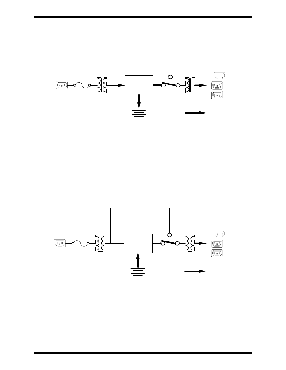
Power flow in AC input mode
The above illustration shows circuit power flow in the ac input mode. The UPS
unit's rectifier, included in a boost chopper circuit, converts ac input power to dc
power. This dc power runs the unit's transistor inverter and charges the batteries.
The boost chopper circuit maintains a constant voltage, with current limiting, for
charging the batteries and assures proper sine waveform generation for the
output current. The unit's batteries are maintained in a constantly charged state
when the UPS is in the normal operation mode. On the front panel, LED's labeled
"On Line" and "AC Input" should be on and the "Fault" LED should be off
(See Section 9.2 Panel Layout).
5.1.2
Battery Backup Mode
Power flow in battery backup mode
The above illustration shows circuit power flow in battery backup mode. When
commercial ac power failures occur, the UPS's batteries instantly begin supplying
dc voltage to the UPS's main inverter circuit. This circuit changes (inverts) the dc
power into ac power. The ac power is available at the unit's output receptacles.
This back-up process will continue until the UPS's battery voltage drops below a
specific minimum level. When this occurs, the batteries will stop supplying power
to the load. This minimum level is the rated minimum voltage (Vmin). The rated
battery voltage chart in section 5.6 (See Section 5.7 for battery backup time)
shows (Vmin). On the front panel, LED's labeled “AC Input” and “Fault” should be
off. The “On Line” and “Backup” LED’s should be on (See Section 9.2 Panel
Layout).
5 - 1
UPS batteries
Bypass circuit
UPS
main
circuit
UPS
receptacles
(rear panel)
= power flow
-
IEC-320
IEC-320
Power
input plug
Fuse
Input
Transformer
+
UPS batteries
Bypass circuit
UPS
main
circuit
UPS
receptacles
(rear panel)
= power flow
-
IEC-320
IEC-320
Power
input plug
Fuse
+
Output
Transformer
Output
Transformer
Input
Transformer
*Isolation only
for 1500 plus
series (600VA)
*Isolation only
for 1500 plus
series (600VA)