Configuration, Group b dip switches – Tripp Lite UT Series User Manual
Page 6
6R
Connect Remote Control—OPTIONAL
An 8-conductor telephone style receptacle on the front panel is included for use with an optional remote control module (included). The remote module
allows the Inverter to be mounted in a compartment or cabinet out of sight, while operated conveniently from within the cab of your vehicle. See
instructions packed with the remote control module.
Connect Battery Temperature Sensing Cable—OPTIONAL—(Select models only)
The battery temperature sensing function prolongs battery life by adjusting the charge float voltage level based on battery temperature. Connect the sensor
cable (the cable, included, has an RJ style connector on one end and a black sensor on the other) to the RJ style jack located on the side of the Inverter
labeled “Remote Temp. Sense.” With user-supplied electrical or duct tape, affix the sensor to the side of the battery below the electrolyte level. Make sure
that nothing, not even tape, comes between the sensor and the side of the battery. To guard against false readings due to ambient temperature, place the
sensor between batteries, if possible, or away from sources of extreme heat or cold. If the sensor cable is not used, the Inverter will charge according to its
default 25º C values.
Utilize Automatic Generator Starter Capability—OPTIONAL—(Select models only)
Although not typically applicable to utility/work truck situations, select Inverter models offer an RJ type modular jack on the
side panel labeled “Generator Start.” If your current fleet is already equipped with generators, select Tripp Lite Utility/Work
Truck Inverters provide your crews the option of quiet power for residential environments or late-night job sites. When wattage
loads are within the Inverter's ratings, crews can avoid the power overkill, fuel consumption, fumes and noise of generator use.
To tie the Inverter and generator together, simply connect the generator's AC power output to the Inverter's AC input. The Inverter will automatically charge
the battery when generator power is available, and generator power will automatically pass-through for use via the Inverter's GFCI receptacles or hardwire
terminals (depending on model). To automatically activate the generator when battery voltage runs low, attach to vehicle generator ON/OFF switching
mechanism with user-supplied cable (see Pin Configuration Diagram). Once attached, the interface will allow the Inverter to automatically switch a vehicle
generator on when connected battery voltage levels are low (11.6 VDC) and switch it off when battery voltage levels are high (14.1 VDC).
Configuration
(continued)
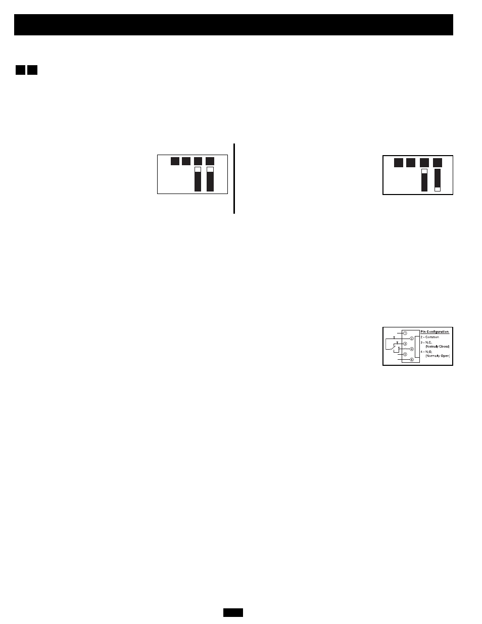
Set Battery Charger Limiting—OPTIONAL
“Most Limiting” (#B2 & #B1 Up): Charger-
limiting takes effect the moment any 120V AC
load is applied; charger output falls gradually
from full output at no 120V load passing
through to no output at full load (factory
setting).
Note: UT1250UL models may only be set to “Most Limiting.”
“Less Limiting” Charger-limiting begins when
the Inverter/ Charger’s load reaches 33% of the
Inverter/ Charger’s load rating. Charger output
falls gradually from full output at 33% of the
Inverter/Charger’s load rating to about 40% of
full output at full load.
B1
B2
B3
B4
B1
B2
B3
B4
Group B DIP Switches
Battery Charger Limiting
Your Inverter/Charger features a high-output battery charger that can draw a significant amount of AC power from your utility source or generator when
charging at its maximum rate. If the unit is simultaneously supplying its full AC power rating to connected heavy electrical loads and charging at its
maximum rate, the AC input circuit breaker could trip, resulting in a complete shutoff of pass-through utility power.
To reduce the possibility of tripping this breaker, your Inverter/Charger may be set to limit charger output automatically. This keeps the sum of the unit's
AC load and charge power within the circuit breaker's rating. The charger-limiting function has two settings, enabling you to reduce charger draw as needed
to prevent the AC input circuit breaker from tripping. The figures below show how to set your unit's DIP Switches to enable battery charger limiting.
B1
B2