Configuration, Group a dip switches (all models) – Tripp Lite UT Series User Manual
Page 5
5R
Configuration
Note: Tripp Lite recommends that users only change settings for the DIP switches and controls described below. Additional DIP switches and
controls located in the unit's DIP switch panel or in other areas are preset to optimize the unit's operation. Setting these DIP switches or controls
may adversely affect the unit's operation.
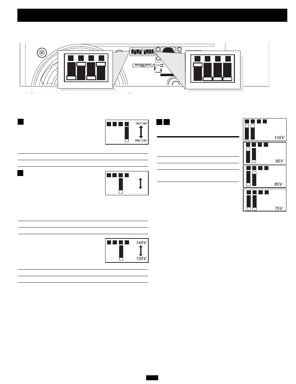
Select Battery Type—REQUIRED
(All models)
CAUTION: The Battery Type DIP Switch setting must
match the type of batteries you connect, or your batteries
may be degraded or damaged over an extended period of
time. See “Battery Selection,” p. 6 for more information.
Battery Type
Switch Position
Gel Cell (Sealed) Battery
Up
Wet Cell (Vented) Battery
Down (factory setting)
Select Charger Enable/Inhibit
(750 and 1250 models only)
Switch is present to ENABLE, which
permits continuous battery charging. If you
are connecting your unit to batteries with a
separate charger, you may set this switch to
INHIBIT to disable its built-in charger to
prevent overcharging.
Charger Status
Switch Position
Inhibit
Up
Enable
Down (factory setting)
Select High AC Input Voltage Point for
Switching to Battery—OPTIONAL
(2012 model only)
Voltage
Switch Position
145V
Up
135V
Down (factory setting)
A1
A2
A3
A4
A1
A2
A3
A4
INHIBIT
ENABLE
INPUT C/B 10A
OUTPUT C/B 12A
B4
B3
B2
B1
A4
A3
A2
A1
Group B Dip Switches (Not on 612 Models)
Group A Dip Switches (All Models)
Group A DIP Switches (All Models)
Using a small tool, configure your Inverter/Charger by setting the four Group A DIP Switches (located on the front panel of your unit; see diagram) as
follows:
A1
A2
* Most of your connected appliances and equipment will perform adequately when your Inverter/Charger’s Low AC Input Voltage Point (DIP Switch #3 and #4 of Group A) are set to 95V. However, if the unit frequently switches to
battery power due to momentary low line voltage swings that would have little effect on equipment operation, you may wish to adjust this setting. By decreasing the Low AC Voltage Point, you will reduce the number of times your
unit switches to battery due to voltage swings.
Select Low AC Input Voltage Point
for Switching to Battery—
OPTIONAL*
Switch
Voltage
Position
105V
#A4 Up & #A3 Up
95V
#A4 Up & #A3 Down
85V
#A4 Down & #A3 Up
75V
#A4 Down & #A3 Down
(factory setting)
A1
A2
A3
A4
A1
A2
A3
A4
A1
A2
A3
A4
A1
A2
A3
A4
A3
A4
A1
A2
A3
A4