Appearance – Toshiba ETB004Z User Manual
Page 7
E6581341
6
1. Name and function of each section
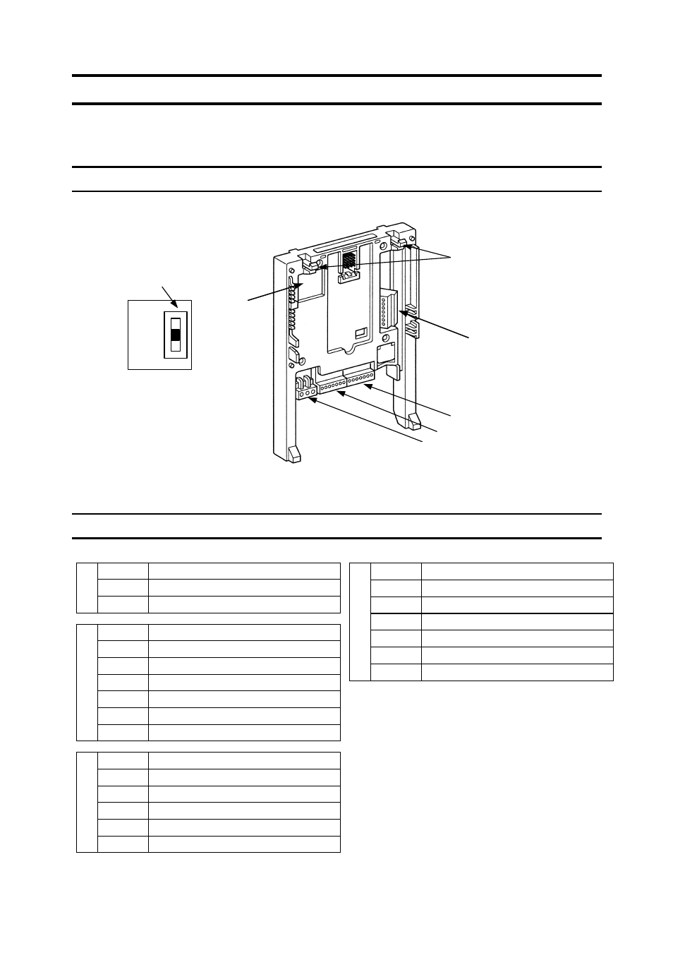
Following figure shows appearance and name of each section of the expansion IO card
option.
1.1. Appearance
1.2. Name of each section (terminal)
R2A
Programmable relay output 2
R2B
Programmable relay output 2
T
B
1
R2C
Programmable relay output 2
N10
Analog input setting power output -10V
AI1+
Differential analog current input (+)
AI1-
Differential analog current input (-)
AI2
Current or voltage analog input
CCA
Analog input/output signal equipotential (0V)
MON1
Multifunction programmable analog output 1
T
B
2
MON2
Multifunction programmable analog output 2
P24/PLC
Common terminal of extension terminal input
LI5
Extension terminal input LI5
LI6
Extension terminal input LI6
LI7
Extension terminal input LI7
LI8
Extension terminal input LI8
T
B
3
CC
Digital signal equipotential (0V)
TH2+
PTC input terminal (+)
TH2-
PTC input terminal (-)
RP
Pulse train input terminal
OUT5
Multifunction programmable open collector output 5
OUT6
Multifunction programmable open collector output 6
NO2
Output 5 and 6 common terminal
T
B
4
CC
Digital signal equipotential (0V)
TB4
Inverter cover hook for the fixation
SINK/SOURCE
Select SW
SINK(INT)
SOURCE
SINK(PLC)
TB1
TB2
TB3