Toshiba ETB004Z User Manual
Page 10
E6581341
9
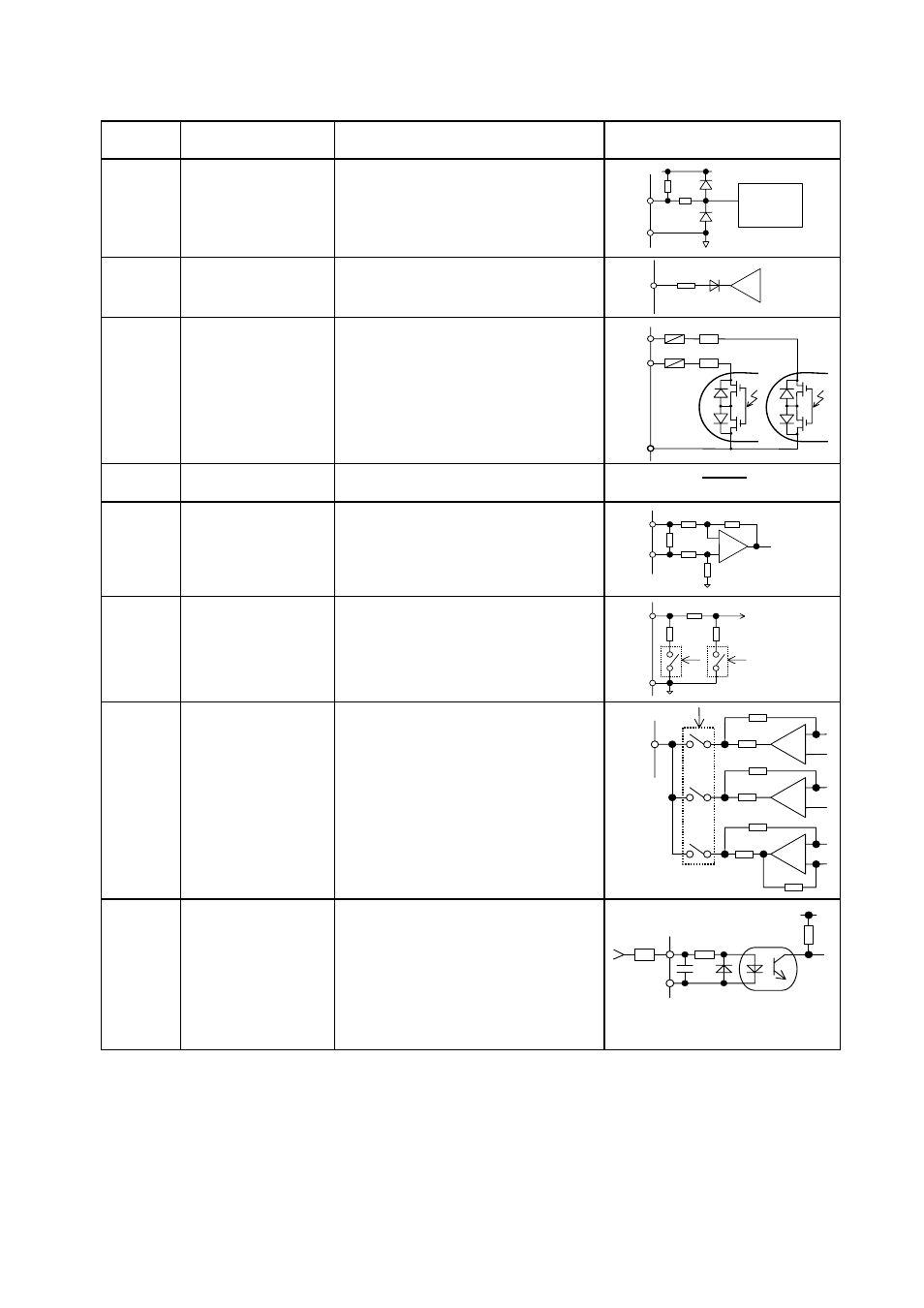
Terminal
symbol
Function Electrical
specification Internal
circuit
TH2+
TH2-
Thermal trip input
The resistance between TH2+ and
TH2-
Tripping value: about under 50 ohm
or over 3k ohm
Reset value: about 1.8k ohm
Voltage
detection
circuit
3k
TH2+
P5
TH2-
10k ohm
N10
-10V power supply
DC-10V - 10mA
N
10
OP
100 ohm
OUT5
OUT6
NO2
Multifunction
programmable
open collector
output.
Open collector output
Drive current
External power supply used : 50mA
Internal power supply used : 20mA
Drive voltage
12V min - 30V max
Isolated other circuit.
20 ohm
OUT5
OUT6
20 ohm
NO2
CC
Common to
input/output
Digital signal equipotential (0V)
terminal for the control circuit
AI1+
AI1-
Differential current
input
Current input :
Equal or under 20mA
Voltage :
Differential input voltage under 5V
Input voltage from –10V to 10V
AI1-
OP
AI1+
242Ω
AI2+
CCA
Analog input
Current input :
Equal or under 20mA
Voltage input :
0 to 10V
AI2
15k ohm
CCA
242
16.2k ohm
MON1
MON2
Monitor output
Multifunction programmable analog
output.
-10V - 10V output
0V - 10V output
0mA - 20mA output
-10V - 10V
OP
MON1
MON2
121 ohm
OP
121 ohm
OP
68 ohm
0 - 10V
0 - 20mA
RP
Pulse train input
Input pulse
Voltage : 5Vmax
Current : 15mA max
Frequency : 30kHz max
Duty : 50±10%
The resistor is needed when input
voltage is over 5V to 30V if the
current is under maximum current.
235
CC
RP
R
Vf = 1.3 - 1.85V
(at 10mA)
Von > 3.5V
Voff < 1.2V
4700pF