Omega Vehicle Security LVP-51 Series User Manual
Page 8
8
ELECTRICAL
Step Five
Supply Voltage: The supply voltage to the LVP‐51‐R level switch should never exceed a maximum of 36 VDC.
OMEGA ENGINEERING controllers have a built‐in 13.5 VDC power supply which provides power to all of
OMEGA ENGINEERING’s electrically powered sensors. Alternative controllers and power supplies, with a
minimum output of 12 VDC up to a maximum output of 36 VDC, may also be used with the level switch.
Required Cable Length: Determine the length of cable required between the level switch and its point of
termination. Allow enough slack to ensure the easy installation, removal and/or maintenance of the sensor.
The cable length may be extended up to a maximum of 1000 feet, using a well‐insulated, 14 to 20 gauge
shielded four conductor cable.
Wire Stripping: Using a 10 gauge wire stripper, carefully remove the outer layer of insulation from the last 1‐
1/4" of the sensor's cable. Unwrap and discard the exposed foil shield from around the signal wires, leaving
the drain wire attached if desired. With a 20 gauge wire stripper, remove the last 1/4" of the colored
insulation from the signal wires.
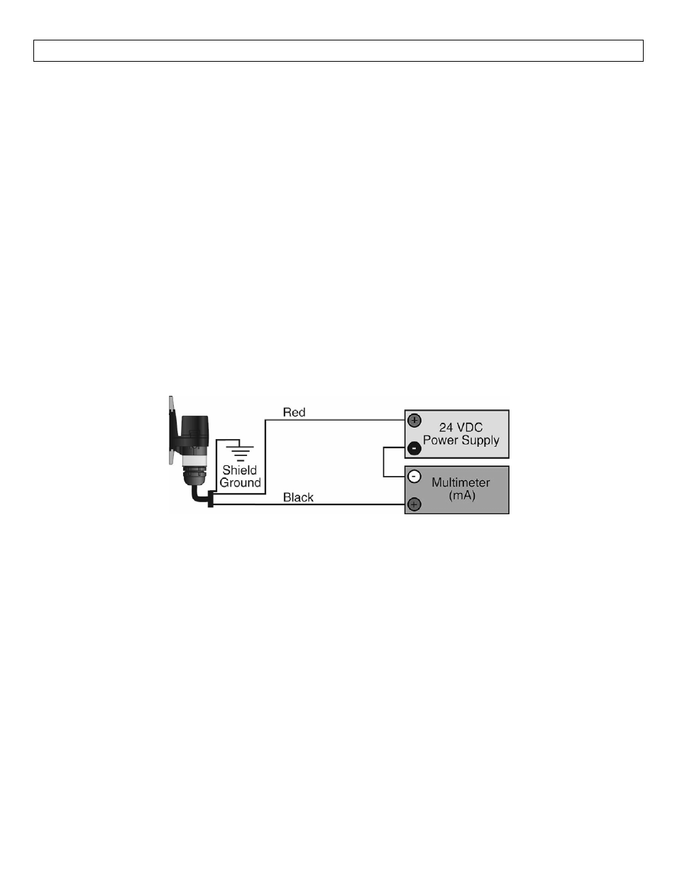
Signal Outputs (Current sensing): The standard method used by OMEGA ENGINEERING controllers; this
technology uses only two wires (Red and Black). The sensor draws 5 mA when it is dry and 19 mA when wet.
NC/NO status must be set by the controller. The White and Green wires are not used.