Omega Vehicle Security LVP-51 Series User Manual
Page 7
7
INSTALLATION
Step Four
OMEGA ENGINEERING's LVP‐51‐R level switch may be installed anywhere on a tank wall using the PE (LVP‐91)
or PP (LVP‐92) bracket that the switch slides into. The bracket comes with adhesive on the tank side that is
sufficient to hold the sensor in position temporarily while the installation is tested, but for permanent
installation the bracket must be welded, glassed or strapped to the tank. Extra brackets are available from
OMEGA ENGINEERING, so that the level switch may be moved to different locations on the tank by sliding it
into other brackets.
Attach the bracket to the tank:
1. Determine whether the tank is PP or PE. The slide‐in fitting shipped with the sensor is determined by
the part number. If necessary, obtain an additional
bracket.
2. Determine the mounting location for the level switch. The
point of actuation (where the sensor will send a “wet”
signal) is most often at the center of the sensor; however
the actual Point of Actuation (POA) may differ depending
on the application liquid and tank wall characteristics.
After positioning the fitting to check clearances, etc.,
remove the paper protective strips from the adhesive of
the bracket.
3. Press the bracket into place. The adhesive provides a seal
between the sensor and the tank wall, and will hold it in
place during testing and installation. If desired, the sensor may be installed temporarily without
welding the fitting to the wall. If several different locations must be tried before permanent
installation, use double‐sided foam stick tape designed for PP or PE.
4. After the sensor has been tested to verify the POA, weld, glass or strap the bracket to the tank using
standard industrial plastic techniques.
Special note for small round tanks: The bracket may be attached to small, round tanks, as long as the
majority of the bracket is firmly attached to the wall. However, extreme installations may affect the switches
performance.
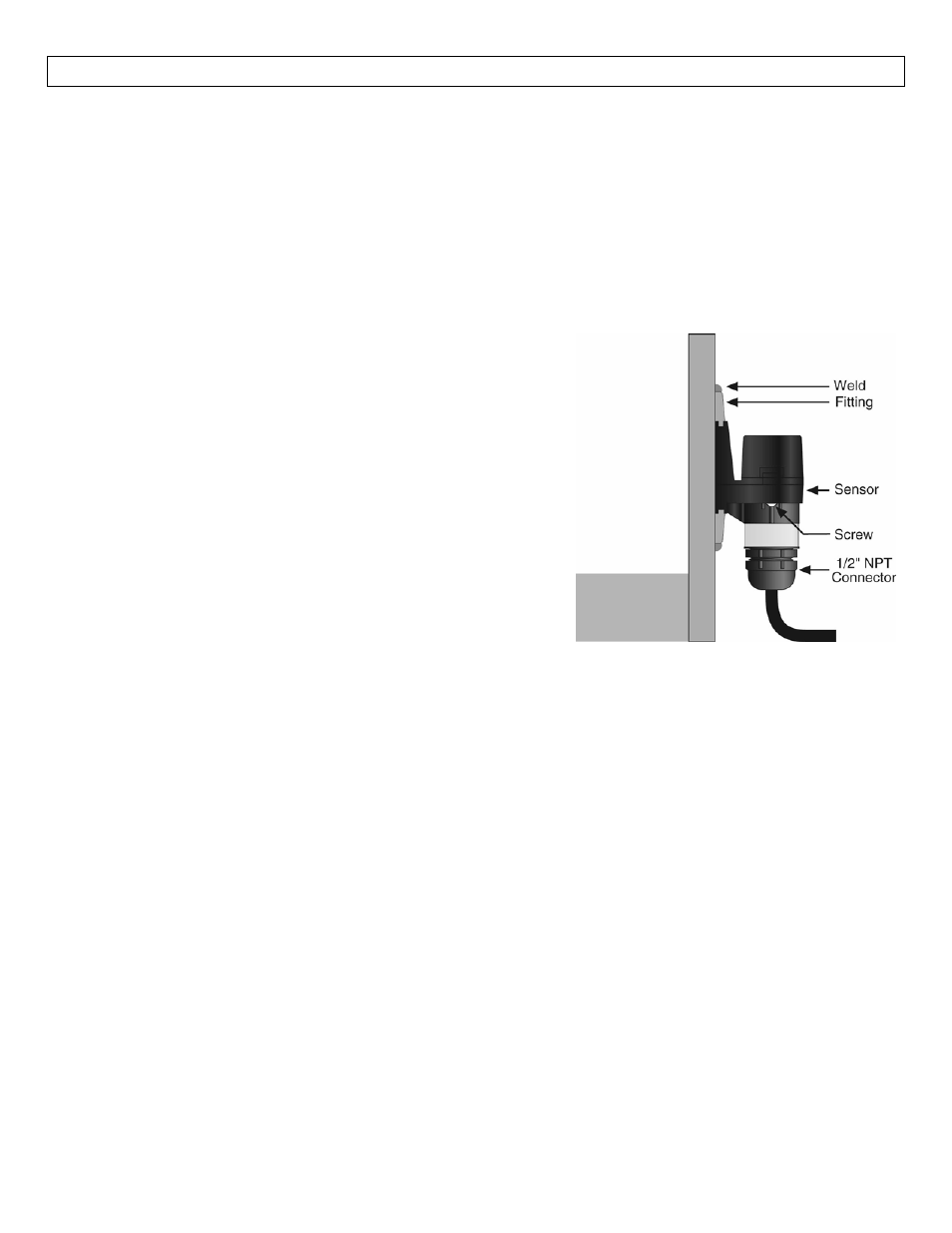
Mount the sensor in the bracket:
1. Slide the sensor into the bracket.
2. After trimming the sensor wire to length if needed by the installation, thread the sensor wire into a
plastic flexible conduit with a 1/2" male fitting. Screw the conduit into the sensor, being careful not to
cross the threads. Do not over tighten the conduit in the sensor as this may break the fitting. Such
damage is not covered by the warranty. Take care while pulling the wire through conduit that no
excessive tension is placed on the sensor end of the wire, so that the wire is not broken from the
sensor housing.
3. Connect the sensor wire to the controller following the instructions in its manual. See the following
Wiring Section for detailed wiring instructions.