Omega Vehicle Security LVP-51 Series User Manual
Page 11
11
WIRING (continued)
Step Six
Wiring the Relay Output: The LVP‐51‐R requires 12 ‐ 36 VDC power to operate the sensor and switch the
relay. All illustrations below identify a Dry switch state as the normal position of the relay.
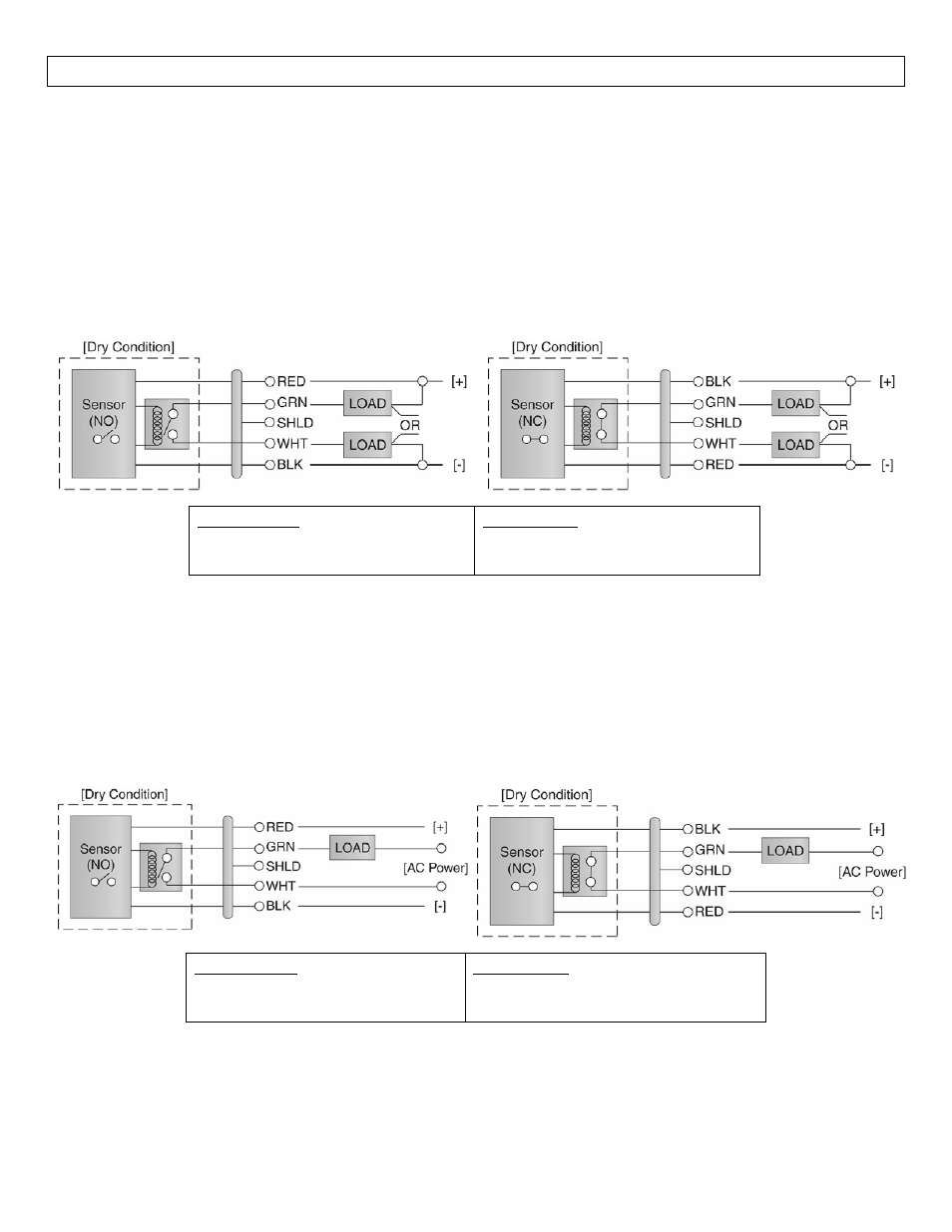
Switching a Normally Open DC Load:
The Red wire connects to Positive (+) of the power
supply and the Black wire connects to Negative (‐).
The LOAD can be attached to either the Green or
White wires. Complete the circuit by connecting the
Green to (+) VDC power or White to (‐) VDC power
(see illustration below).
Switching a Normally Closed DC Load:
The Black wire connects to Positive (+) of the power
supply and the Red wire connects to Negative (‐). The
LOAD can be attached to either the Green or White
wires. Complete the circuit by connecting the Green
to (+) VDC power or White to (‐) VDC power (see
illustration below).
Sensor Power
[RED & BLK wires] / 36 VDC Max.
5 ±1mA Dry / 20 ±1mA Wet
Relay Rating
[GRN & WHT wires] / 60 VA
Switching a Normally Open AC Load:
The Red wire connects to Positive (+) of the DC
power supply and the Black wire connects to
Negative (‐). The LOAD can be attached to the
Green wire and the Hot of the VAC power. Connect
the White to the Neutral of the VAC power (see
illustration below).
Switching a Normally Closed AC Load:
The Black wire connects to Positive (+) of the DC power
supply and the Red wire connects to Negative (‐). The
LOAD can be attached to the Green wire and the Hot of
the VAC power. Connect the White to the Neutral of
the VAC power (see illustration below).
Sensor Power
[RED & BLK wires] / 36 VDC Max.
5 ±1mA Dry / 20 ±1mA Wet
Relay Rating
[GRN & WHT wires] / 60 VA