Omega Vehicle Security LVP-51 Series User Manual
Page 12
12
WIRING (continued)
Step Six
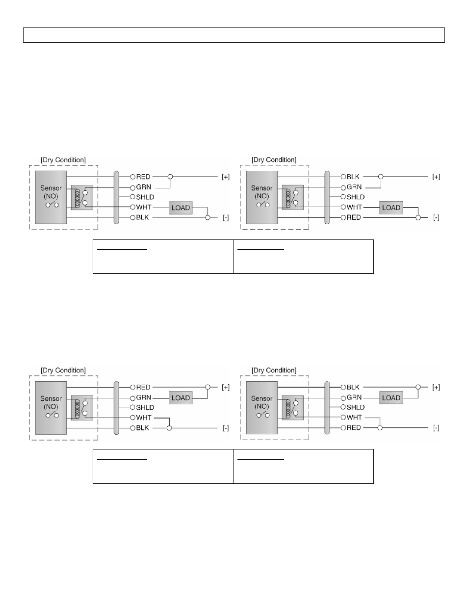
Wiring as a P‐Channel or N‐Channel output: The LVP‐51‐R can be substituted for either a P‐Channel (PNP,
sourcing) output or an N‐Channel (NPN, sinking) output.
Normally Open DC Load as a P‐Channel Output:
The Red wire connects to Positive (+) of the power
supply and the Black wire connects to Negative (‐).
The Green wire is jumped to the Red wire while the
White wire is connected to the LOAD. Jumper the
LOAD to the Negative (‐) to complete the circuit.
Normally Closed DC Load as a P‐Channel Output:
The Black wire connects to Positive (+) of the power
supply and the Red wire connects to Negative (‐). The
Green wire is jumped to the Black wire while the
White wire is connected to the LOAD. Jumper the
LOAD to the Negative (‐) to complete the circuit.
Sensor Power
[RED & BLK wires] / 36 VDC Max.
5 ±1mA Dry / 20 ±1mA Wet
Relay Rating
[GRN & WHT wires] / 60 VA
Normally Open DC Load as a N‐Channel Output:
The Red wire connects to Positive (+) of the power
supply and the Black wire connects to Negative (‐).
The White wire is jumped to the Black wire while the
Green wire is connected to the LOAD. Jumper the
LOAD to the Positive (+) to complete the circuit.
Normally Closed DC Load as a N‐Channel Output:
The Black wire connects to Positive (+) of the power
supply and the Red wire connects to Negative (‐). The
White wire is jumped to the Red wire while the White
wire is connected to the LOAD. Jumper the LOAD to
the Positive (+) to complete the circuit.
Sensor Power
[RED & BLK wires] / 36 VDC Max.
5 ±1mA Dry / 20 ±1mA Wet
Relay Rating
[GRN & WHT wires] / 60 VA