Renesas Single-Chip Microcomputer M34519T-MCU User Manual
Page 22
( 20 / 36 )
(2) Connection to the IC socket for 32-pin SDIP
Attach pitch converter board M34513T-PTCA to the 50-wire normal-pitch cable, and connect it
to an IC socket for 32-pin SDIP on the target system.
Use the following products:
(1) 100-wire half-pitch cable (40 cm)
(2) Pitch converter board PCA4029
(3) 50-wire normal-pitch cable (10 cm)
(4) Pitch converter board M34513T-PTCA
Table 3.10 lists the connector assignments of pitch converter board M34513T-PTCA. When
attaching the pitch converter board, check the No. 1 pin positions of the cable and the connector.
Be careful not to connect the cable in a wrong direction.
Table 3.10 Connector assignments of pitch converter board M34513T-PTCA
*1: VDD is not used for inputting power from the target system, but it is used for outputting power
from the power circuit on the M34519T-MCU to the target system. Output of VDD (on/off) is set by
switch SW1. For details, refer to "3.3 Switches" (page 13).
*2: XIN is input from oscillator board OSC-2 on the M34519T-MCU, and it is not input from the
oscillator circuit on the target system. To change a system clock frequency, change the frequency of
oscillator board OSC-2.
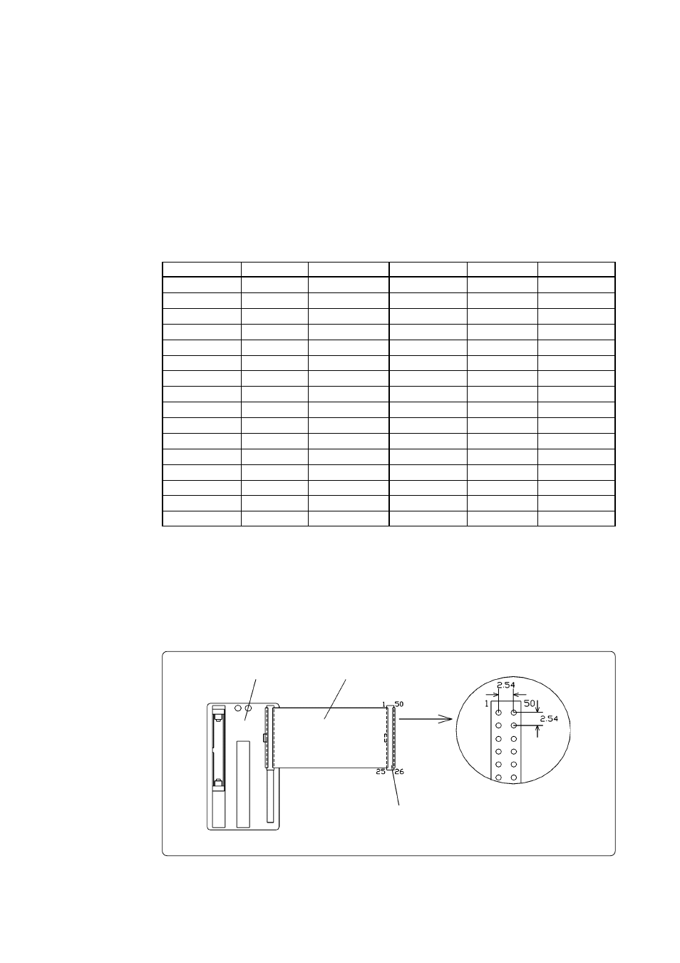
Figure 3.8 Pin layout of the 50-wire normal-pitch cable
PCA4029
50-wire normal-pitch cable
50-pole dual-in-line socket
Unit: mm
Connector pin No.
MCU pin No.
Signal
Connector pin No.
MCU pin No.
Signal
1
1
D0
32
32
P13
2
2
D1
31
31
P12
3
3
D2
30
30
P11
4
4
D3
29
29
P10
5
5
D4
28
28
P03
6
6
D5
27
27
P02
7
7
D6/CNTR0
26
26
P01
8
8
D7/CNTR1
25
25
P00
9
9
P20/SCK
24
24
P63/AIN3
10
10
P21/SOUT
23
23
P62/AIN2
11
11
P22/SIN
22
22
P61/AIN1
12
12
RESET
21
21
P60/AIN0
13
13
CNVSS
20
20
P31/INT1
14
14
XOUT
19
19
P30/INT0
15
15
XIN*
2
18
18
VDCE
16
16
VSS
17
17
VDD*
1