4 check pins, 5 connectors – Renesas Single-Chip Microcomputer M34519T-MCU User Manual
Page 16
( 14 / 36 )
3.4 Check Pins
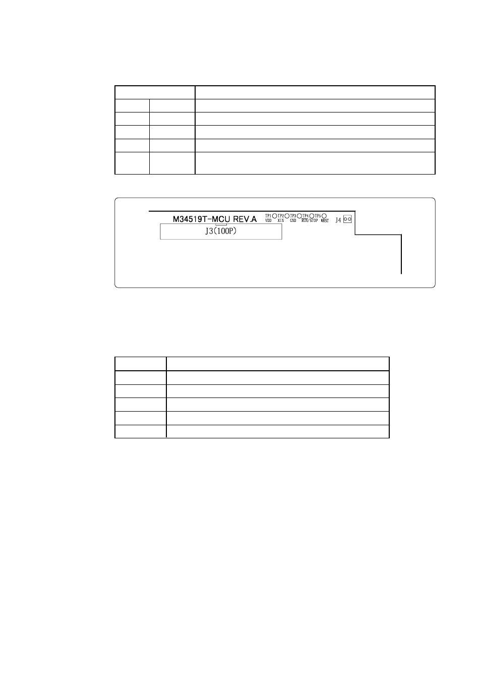
Table 3.3 lists the check pins of the M34519T-MCU, and Figure 3.3 shows their positions.
Table 3.3 Check pins
Figure 3.3 Positions of the check pins
3.5 Connectors
Table 3.4 lists the functions of the connectors of the M34519T-MCU.
Table 3.4 Connectors
Connector
J1
J2
J3
J4
J6
Function
Connects the evaluation MCU bus.
Connects the monitor CPU bus.
Connects the target system. (100-pin)
Connects external trigger signal. (2-pin)
Connects oscillator circuit board OSC-2. (4-pin)
Pin
Function
Outputs +3 V or +5 V (MCU voltage) according to the setting of SW3.
Outputs a system clock input to the evaluation MCU.
Ground
Held low when a user program is executed, held high when it is stopped.
Held high when WRST instruction is executed, and you can check the
initialization cycle of the watchdog timer by observing pulse widths.
TP1
TP2
TP3
TP4
TP5
VDD
XIN
GND
RUN/STOP
WRST
- Single-Chip Microcomputer M34551T2-MCU (42 pages)
- M3T-FLX-80NRA (6 pages)
- 70 (162 pages)
- M16C/30P (102 pages)
- PROM Programming Adapter PCA7427G02 (20 pages)
- R0E572110CFK00 (40 pages)
- H8/325 Series (20 pages)
- Single-Chip Microcomputer H8/36079 (27 pages)
- Direct Dummy IC M3T-DIRECT100S (4 pages)
- M3A-2152 (95 pages)
- PCA7755D (6 pages)
- M16C/6N5 (106 pages)
- SH7085 (50 pages)
- QFP-144 (23 pages)
- H8/3834 Series (22 pages)
- RSKM16C62P (3 pages)
- H8/33937 (22 pages)
- Single-Chip Microcomputer H8SX/1622 (5 pages)
- E6000 (29 pages)
- PCA7400 (18 pages)
- PCA4738FF-64 (20 pages)
- SuperH HS7339KCU01HE (43 pages)
- M16C FAMILY (103 pages)
- PCA7412F-100 (20 pages)
- 4513 (210 pages)
- M34551E8FP (16 pages)
- Dummy IC M3T-SSOP36B-450 (4 pages)
- Emulation Pod M30100T3-RPD-E (52 pages)
- Converter Board for M30102 M30102T-PTC (4 pages)
- SH7145 (31 pages)
- HS1653ECN61H (36 pages)
- Converter Board R0E521276CFG00 (4 pages)
- PCA7302E1F-80 (18 pages)
- H8/3814 Series (21 pages)
- H8S/2646 Series (20 pages)
- SuperHTM Family SH7125 Series (40 pages)
- M30262T-PTC (4 pages)
- SH7670 (82 pages)
- H8/3864 Series (20 pages)
- Emulator System M3T-MR100 (306 pages)
- 38K0 (6 pages)
- PLQP0176KB-A (40 pages)
- Direct Dummy IC M3T-DIRECT80S (6 pages)
- PCA4738L-80A (26 pages)
- Converter Board R0E5212BACFG00 (6 pages)