Caution – Renesas Single-Chip Microcomputer M34519T-MCU User Manual
Page 18
( 16 / 36 )
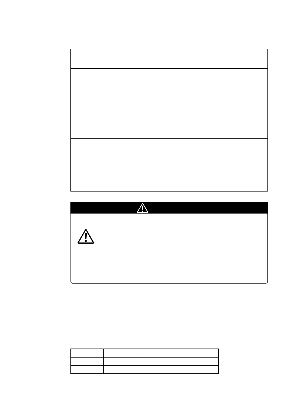
Some signals which are connected to the target system are emulated by the M34519T-MCU. Table
3.6 lists the connections of the target system and each pin.
Table 3.6 Connection of the target system and each pin
CAUTION
Notes on Connecting the Evaluation MCU and Target System:
• VDD is not used for inputting power from the target system, but it is used for
outputting power from the power circuit on the M34519T-MCU to the target system.
Output of VDD (ON or OFF) is set by switch SW1, and the voltage (3 V or 5 V) is
set by switch SW3.
• XIN is input from the oscillator board OSC-2 on the M34519T-MCU, and it is not
input from the oscillator on the target system. To change a system clock frequency,
use another oscillator board OSC-2 (included) with other necessary parts.
(2) Connector J4
Connect the 2-wire external trigger cable included with the M34519T-MCU to 2-pin connector
J4 for external trigger signal. Connect the black clip of the 2-wire external trigger cable to GND,
and use the white clip for external trigger signal input.
External trigger signal is used for event input of external trigger breaks or external trace points.
Table 3.7 lists the pin assignments of connector J4.
Table 3.7 Pin assignments of connector J4
Item
Pins connected directly to the target system
(12 types 23 pins)
Signal
4519 Group
• P20/SCK
• P21/SOUT
• P22/SIN
• P30/INT0, P31/INT1
• P32, P33
• P40/AIN4--P43/AIN7
• P50--P53
• P60/AIN0--P63/AIN3
• D6/CNTR0
• D7/CNTR1
• VDCE
• VSS
• P00--P03
• P10--P13
• D0--D5
• RESET
• VDD
• XIN
• XOUT
• CNVSS
4584 Group
• P20--P23
• P30/INT0, P31/INT1
• P40--P43
• P50--P53
• P60/AIN0, P61/AIN1
• P62, P63
• D6/CNTR0
• C/CNTR1
• VDCE
• VSS
Pins connected to the target system via an
emulation circuit etc. (5 types 16 pins)
Pins not connected to the target system
(3 types 3 pins)
Pin No.
1
2
Signal
TRIG
GND
Function
External trigger signal input
GND