Robertshaw 9620 User Manual
Page 5
10. Secure base to wall with supplied screws.
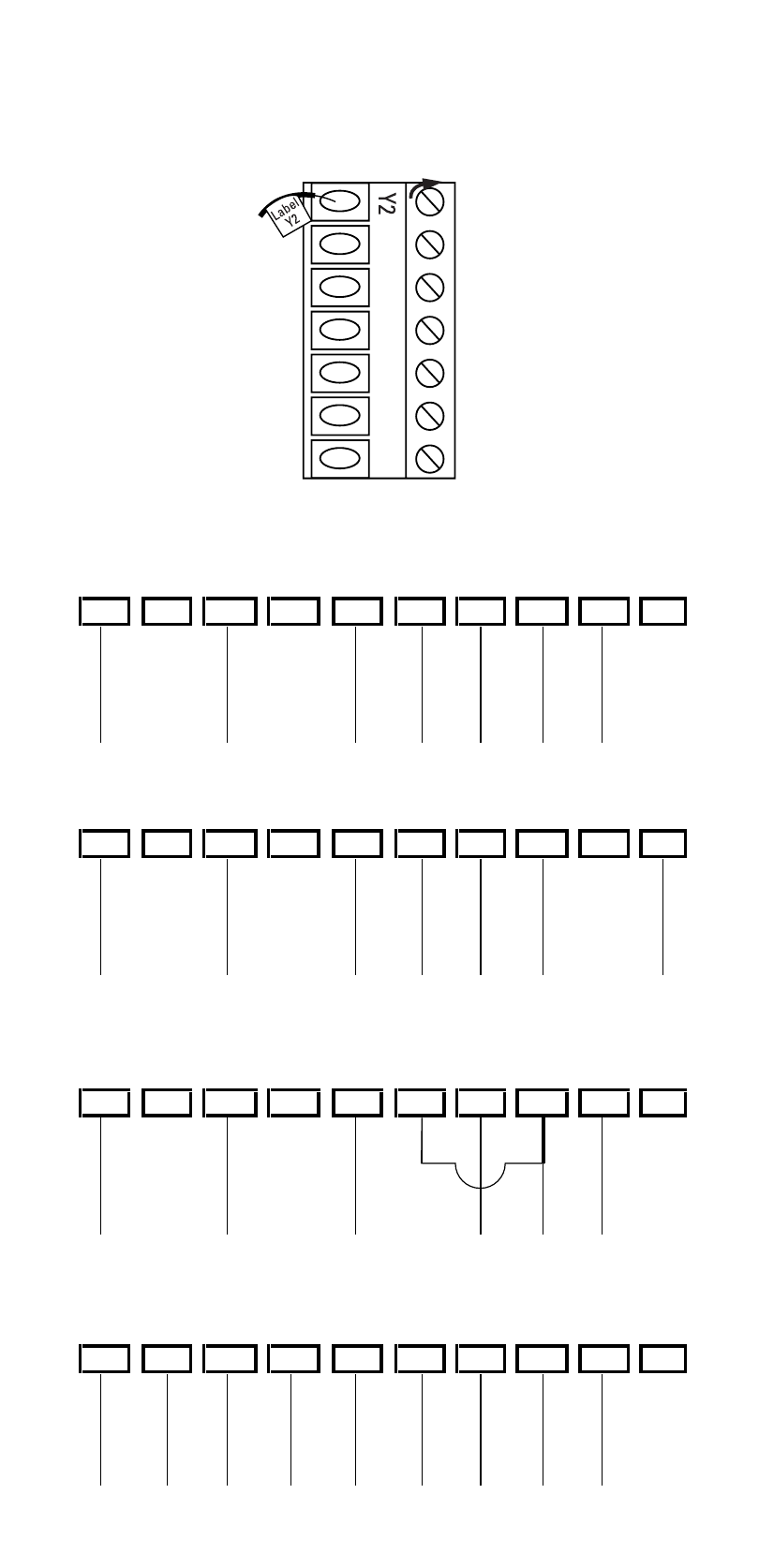
11. Terminal screws are loosened. Insert wires into terminal strip
(Figure 4) matching the label to the corresponding terminal (see
Wiring Diagrams below). Tighten screws.
5
9620 WIRING SAMPLE #1
Y1
E
G
W2
C
L
R
Y2
Typical heat pump with cool active reversing valve and auxiliary/emergency heat.
O
B
B
9620 WIRING SAMPLE #2
C
L
R
Y2
Y1
E
G
W2
O
Typical heat pump with heat active reversing valve and auxiliary/emergency heat.
R
Y2
Jumper
9620 WIRING SAMPLE #3
B
Y1
E
G
W2
C
L
O
Typical heat pump with heat active reversing valve and auxiliary/emergency heat.
Does not have separate wire for emergency heat (jump W2 & E).
O
B
9620 WIRING SAMPLE #4
C
W2
L
R
Y2
Y1
E
G
Typical heat pump with cool active reversing valve, auxiliary/emergency heat
and second stage of cooling. System fault indicator connected (L terminal).
FIGURE 4