Component locations, General information – Raypak MVB 503-2003 User Manual
Page 6
General Information
Table A: Basic Data
6
HIGH VOLTAGE
ELECTRICAL CONNECTIONS
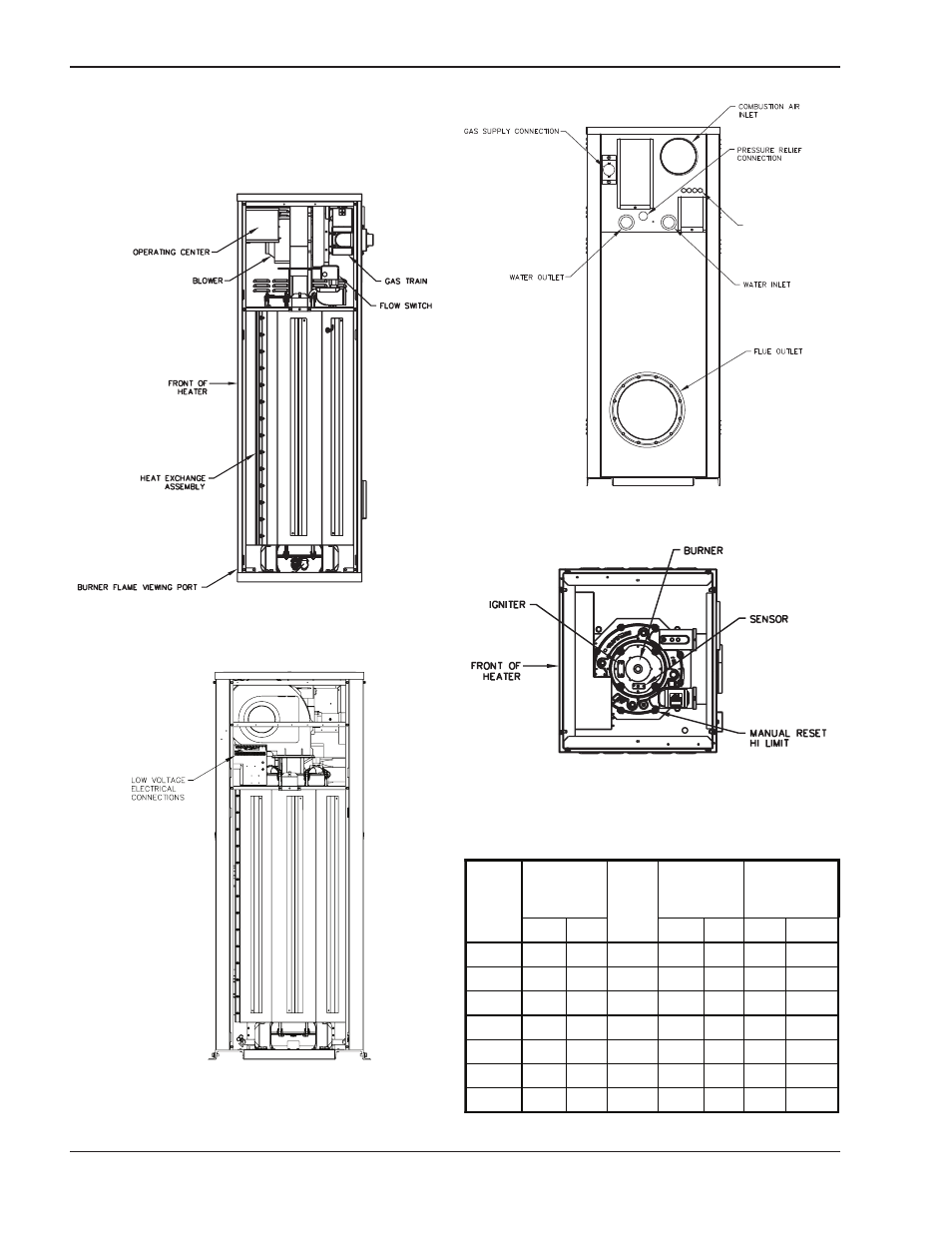
Component Locations
Panels omitted for clarity
Fig. 1: Component Locations – Side
Top panel, blower and gas train omitted for clarity
Fig. 4: Component Locations – Top
Fig. 3: Component Locations – Rear
MBTUH
Input
Gas
Conn.
(NPT)
Vent Size
(in.)
Model
No.
Max. Min.
Water
Conn.
(NPT)
N
P
Flue Intake
503
500
125
2
1
1
6
6
753
750
188
2
1
1
6
6
1003
999
250
2-1/2
1-1/4
1
6
6
1253
1250 312
2-1/2
1-1/4
1
8
8
1503
1500 375
2-1/2
1-1/4
1
8
8
1753
1750 438
2-1/2
2
1
8
8
2003
1999 500
2-1/2
2
1
8
8
Panels omitted for clarity
Fig. 2: Component Locations – Front
See also other documents in the category Raypak Water boiler:
- 240692 (31 pages)
- HIDELTA 992B (68 pages)
- 1000 (74 pages)
- RAYTHERM 962-1826 (2 pages)
- 335 (1 page)
- 504-2004 (4 pages)
- 265 (14 pages)
- 751-1501 (2 pages)
- HI DELTA HD401 (48 pages)
- DEL TA LIMITED 899B (5 pages)
- 2100 - 4001 (2 pages)
- H-0042B (4 pages)
- 2005 (8 pages)
- HI DALTA HD401 (48 pages)
- XFYRE 400 (8 pages)
- 42 & 66 (2 pages)
- 992BE (5 pages)
- 500 (56 pages)
- 182-400 (2 pages)
- Gas Fired Boiler (8 pages)
- MVB 5042004 (56 pages)
- B0147 (43 pages)
- RAYTHERM 0042B (40 pages)
- WH 0090A (28 pages)
- H7 504-2004 (2 pages)
- 503-2003 (60 pages)
- XFYRE NINETY PLUS 850 (8 pages)
- XPAK 85 (68 pages)
- 0066B (38 pages)
- 195A (28 pages)
- Power Vent Raytherm 4001 (2 pages)
- FlexGas (1 page)
- XPAK 120 (12 pages)
- XTHERM 1505 (8 pages)
- RayTherm Commercial Boilers And Water Heater (4 pages)
- 0135B (6 pages)
- RayTemp Hot Water Energy Management Control (30 pages)
- 0090B (39 pages)
- B6000 (51 pages)
- B6000 (2 pages)
- 1001 (76 pages)
- RAYTHERM 133-4001 (44 pages)
- HI DELTA SS HD401 (4 pages)
- XFYRE 300-850 (2 pages)
- 30B (4 pages)