Option links – Renesas RSKM16C6NK User Manual
Page 11
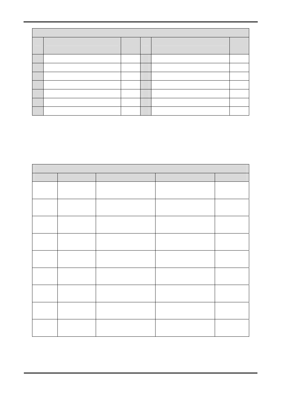
J11
Pin
Circuit Net Name
Device
Pin
Pin
Circuit Net Name
Device
Pin
1 Ground
-
2 5V
Only
-
3 No
Connection
-
4 DLCDRS
70
5
R/W (Wired to Write only)
-
6 DLCDE
69
7 No
Connection
-
8 No
Connection
-
9 No
Connection
-
10 No
Connection
-
11 DLCD4
66
12 DLCD5
65
13 DLCD6
64
14 DLCD7
63
Table 6-5: LCD Module Connections
6.6. Option Links
Table 6-6 below describes the function of the option links associated with Power configuration. The default configuration is indicated by
BOLD text.
Option Link Settings
Reference
Function
Fitted
Alternative (Removed)
Related To
R9 Board
VCC Supply to board from J5
Fit Low ohm resistor to measure
current
R32 Microcontroller
VCC1
Supply to microcontroller
VCC1
Fit Low ohm resistor to measure
current
R33
R33 Microcontroller
VCC2
Supply to microcontroller
VCC2
Fit Low ohm resistor to measure
current
R32
R25
Board VCC1
Board VCC1 connected to
Connector 3V3
Disconnected
R23,28
R28 Board
VCC1 Board VCC1 connected to
Connector 5V
Disconnected
R23,R25
R23 Board
VCC1 Board VCC1 connected to
Connector J5
Disconnected
R25,R28
R26
Board VCC2
Board VCC2 connected to
Connector 3V3
Disconnected
R24,29
R29 Board
VCC2 Board VCC2 connected to
Connector 5V
Disconnected
R24,R26
R24 Board
VCC2 Board VCC2 connected to
Connector J5
Disconnected
R26,R29
Table 6-6: Power Configuration Links
9