Serial port, Lcd module – Renesas RSKM16C6NK User Manual
Page 10
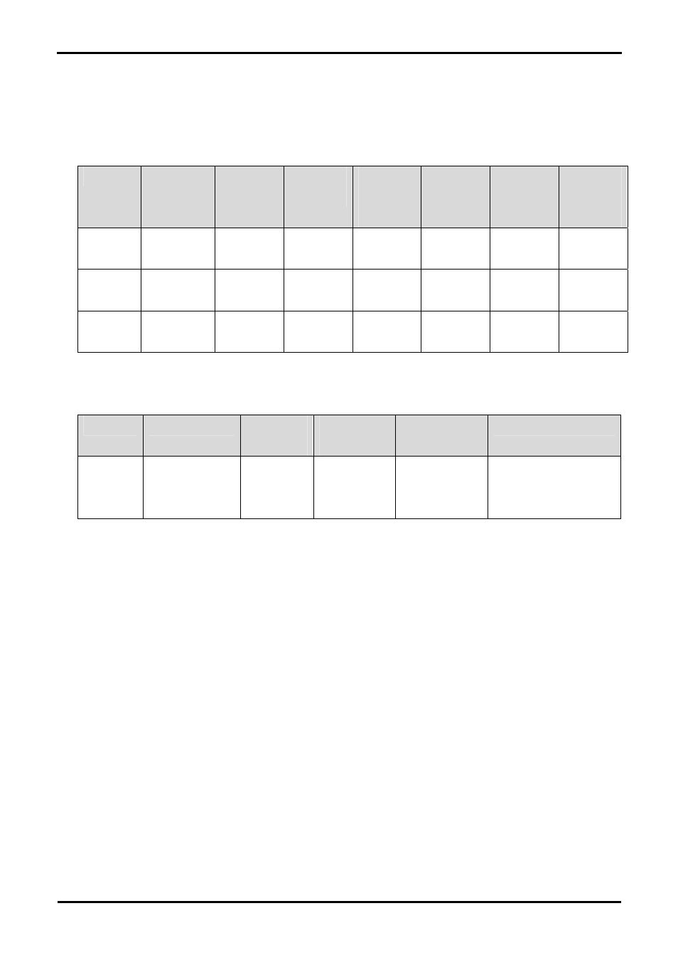
6.4. Serial port
The microcontroller programming serial port 1 is connected to the RS232 connector. A serial port can be used by moving option resistors
and fitting the D connector. This can be connected to serial channel 1 if the E8a is disabled from using channel 1; or serial channel 0 while
the E8a is enabled.
Description
Function
Fit For E8a
Remove for
E8a
Fit for
RS232
Channel 0
Remove for
RS232
Channel 0
Fit for
RS232
Channel 1
Remove for
RS232
Channel 1
TxD1 Programming
Serial Port
R13 R68 R69 R68 R68 R69,
R13
RxD1 Programming
Serial Port
R12 R44 R47 R44 R44 R47,
R12
CLK1 Programming
Serial Port
R14 NA NA NA NA R14
Table 6-3: Serial port connections
If a serial port is used the D-connector U3 must be fitted and the RS232 transceiver enabled.
Description
Function
Fit For RS233
Enable
Remove for
RS233 Enable
Fit For RS233
Disable
Remove for RS233 Disable
RS232
Transceiver
Enable
Disables/Enables
U3 RS232
Transceiver
R42 R39 R39
R42
Table 6-4: RS232 enable
An additional serial port is connected to the application headers.
6.5. LCD Module
An LCD module is supplied to be connected to the connector J11. This should be fitted so that the LCD module lies over J3. Care should be
taken to ensure the pins are inserted correctly into J11.The LCD module uses a 4 bit interface to reduce the pin allocation. No contrast
control is provided; this is set by a resistor on the supplied display module. The module supplied with the RSK only supports 5V operation.
Table 6-5 shows the pin allocation and signal names used on this connector.
8