Roberts Gorden 175 User Manual
Page 53
SECTION 15: R
EPLACEMENT
P
ARTS
45 of 51
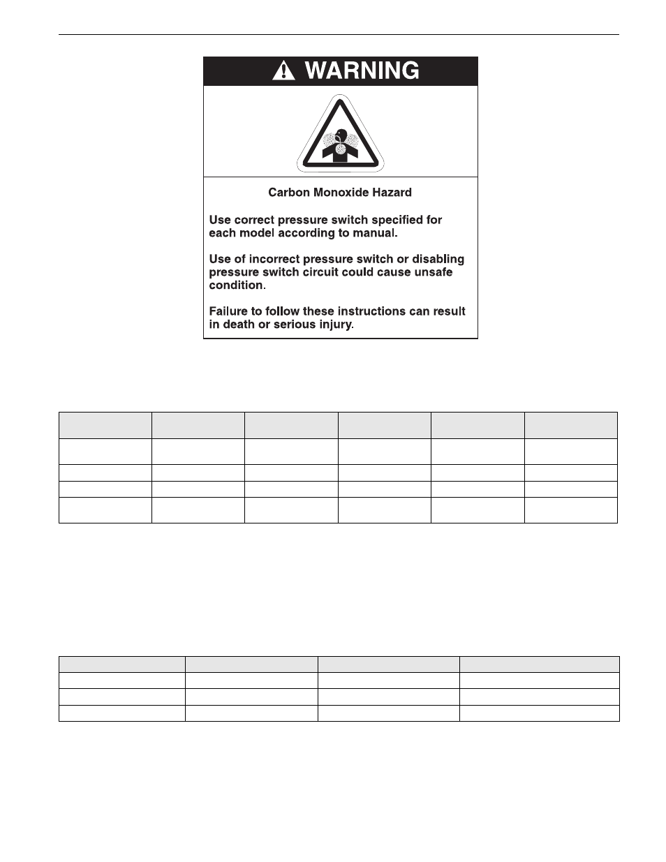
15.7 Pressure Switch
Pull off 3 way connector. Spring open plastic clips of mounting cradle. Replace with correct type of
pressure switch for model. The pressure switches are color coded for each pressure setting.
Carry out a start-up after working on or changing a pressure switch.
See Page 27, Section 11.
15.8 Ignition Control
The control mounts to the electrical plate. Pull out ignition cable and wiring from board, noting their
positions. Release the four mounting standoffs. Refit in reverse. Ensure correct location of ignition cable
and all other wiring.
15.9 Axial Fan/Guard/Motor Assembly
The axial fan unit for the heater is supplied completely assembled and balanced
MODEL
UHA[X][S]
150 - 175
UHA[X][S]
200 - 225
UHA[X][S]
250
UHA[X][S]
300 - 350
UHA[X][S]
400
Pressure Switch
Kit P/N
90439802
90439808
90439803
90439807
90439808
Color Code
yellow
orange
gray
brown
orange
Set Point in. w.c.
.32
.79
.41
.68
.79
Pressure Switch Snap
Ring P/N
90439850
90439850
90439850
90439850
90439850
MODEL
UHA[X][S] 150 - 175
UHA[X][S] 200- 250
UHA[X][S] 300 - 400
Axial Fan Guard
91901104
91901104
91901105
Axial Fan Motor
90600107
90600107
90600106
Axial Fan Blade
90709006
90709006
90709005