Roberts Gorden 175 User Manual
Page 37
SECTION 11: O
PERATION
AND
M
AINTENANCE
29 of 51
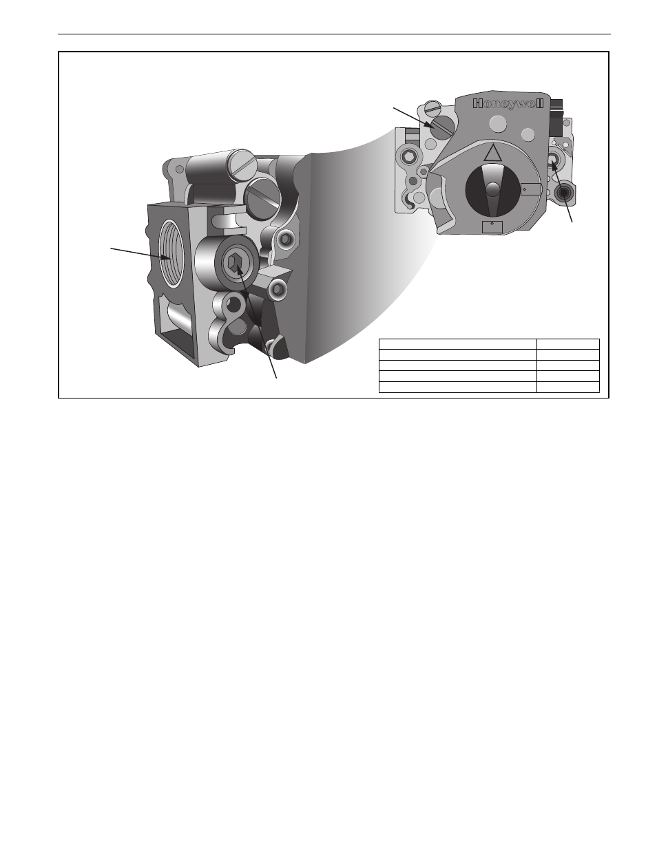
Figure 14: Gas Valve for Models UHA[X][S] 150 - 400
11.2.2 Start-Up the Gas Valve (All Gases)
11.2.2.1 Check Burner Gas Pressure
1. Remove the plug in the outlet (burner) pressure
test point and connect a pressure tap and a
manometer.
2. With the burner firing, measure the pressure on
the manometer. To adjust the burner pressure,
remove the regulator cover from the valve and
turn the regulator adjustment screw to set the
required burner pressure as stated in the
Technical Data Table for the correct gas and
model
on Page 49, Section 16.3.
NOTE: If the correct burner pressure cannot be
reached, then check the inlet pressure to the valve
with the burner firing. See Technical Data Table
on
Page 49, Section 16.3 for inlet pressure
requirement.
Do not continue to adjust the regulator if the
pressure is not changing.
If the inlet pressure is too low to allow correct burner
pressure setting, then the gas inlet pressure must be
corrected before completing the start-up.
Check Gas Rate
1. After burner pressure adjustment, allow the
heater to operate for at least 15 minutes and
then re-check settings. Adjust pressure setting
if necessary.
2. Check gas flow rate at gas meter.
3. Turn off heater and electrical supply.
4. Remove the manometer and refit all covers to
the valve and tighten the screw of the outlet
pressure tap.
11.2.3 Pressure Switch
The pressure switch is factory pre-set for each
model and is not adjustable.
11.2.4 Turning Off the Heater
Set the thermostat to the "OFF" position or lowest
setting and the main burner will stop.
The fan will continue to run until it is stopped
automatically by the fan thermostat.
Do not use a disconnect switch for control of
heater. Disconnect switch will turn off the fan.
Heat exchanger could be damaged. Warranty will
not cover damage to the heat exchanger if
operated improperly. Only use the disconnect
switch for turning off heater for service or during
off-season.
½PSI
IN
C
ON
OFF
Regulator
Outlet
Pressure
Gas Inlet
Inlet Pressure
TOP VIEW
END VIEW
Description
Part Number
Gas Valve 150 - 250 NG
90032505
Gas Valve 150 - 250 LP
90032506
Gas Valve 300 - 400 NG
90032520
Gas Valve 300 - 400 LP
90032521