1 roberts gordon, Figure 31: roberts gordon, Ultravac™ controller components diagram – Roberts Gorden 10081601NA Rev H 12/11 User Manual
Page 62: Part number, Description, Control board (150 style), Relay board, Analog output board, Urv eprom chip (150 style, current version), Plug-in relay
ROBERTS GORDON
®
ULTRAVAC™ C
ONTROLLER
I
NSTALLATION
M
ANUAL
56 of 62
10.1 ROBERTS GORDON
®
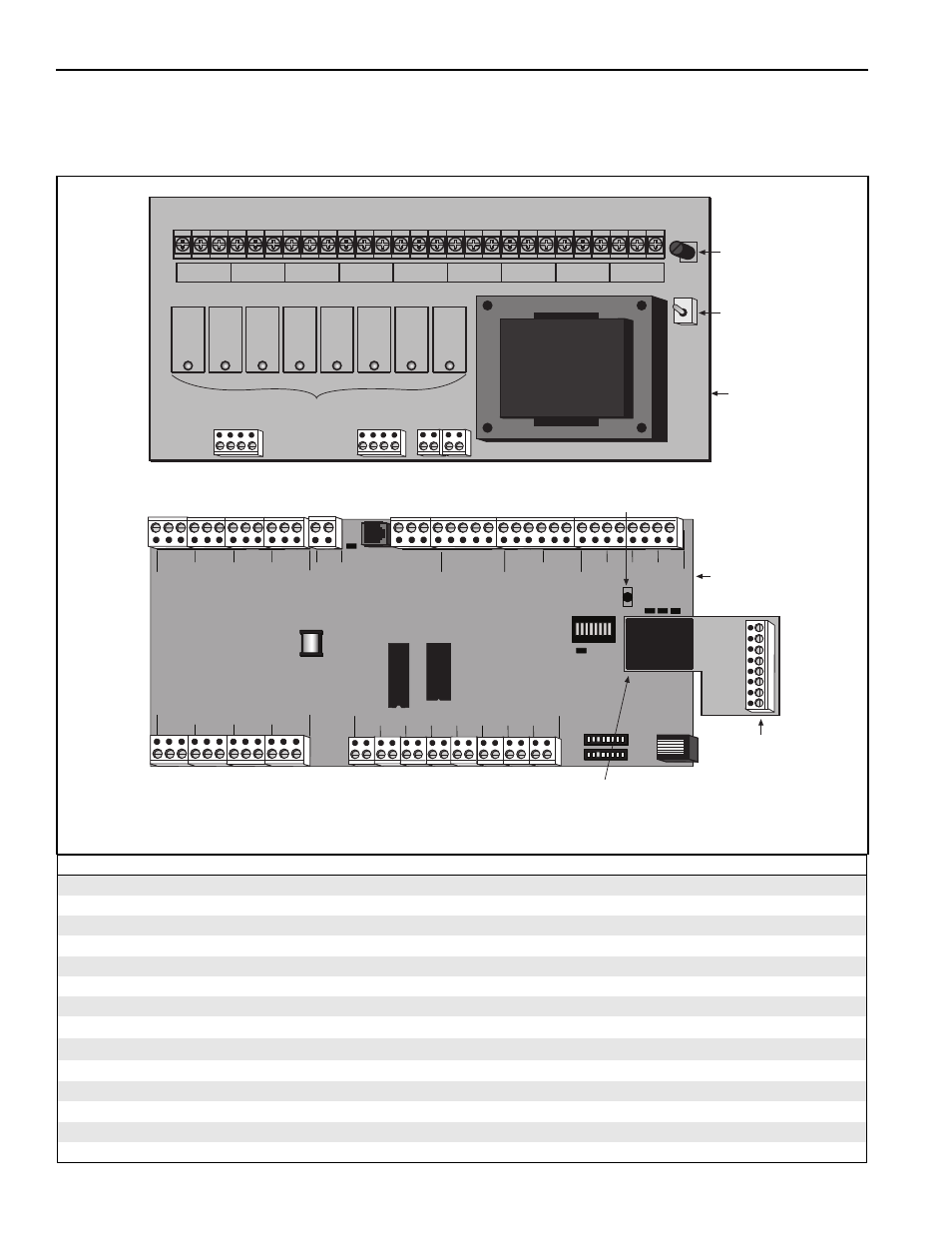
ULTRAVAC™ Controller Replacement Parts
Caution: Use only genuine ROBERTS GORDON
®
replacement parts. Use of parts not specified by
Roberts-Gordon voids warranty.
FIGURE 31: ROBERTS GORDON
®
ULTRAVAC™ Controller Components Diagram
Description
Part Number
Control Board (150 style)
10080102
Relay Board
10080200
Analog Output Board
10080141
URV Eprom Chip (150 Style, current version)
10080122
Plug-In Relay
10080212
Modem Chip (located only on central controller)
10080142
1 A Fuse (Relay Board)
10080211
ROBERTS GORDON
®
ULTRAVAC™ Indoor Sensor °F (not shown)
10081500
ROBERTS GORDON
®
ULTRAVAC™ Outdoor Sensor (not shown)
10081501
ROBERTS GORDON
®
ULTRAVAC™ Indoor Sensor °C (not shown)
10081502
PC Connection Cable Package (not shown)
10080410
RS-485 Converter Package (not shown)
10080430
Kit, TCP/IP Communication Module (not shown)
10080440K
Telephone Sharing Device, 4 port
10080600
+
- 1
+
- 2
+
- 4
+
- 3
+
- 5
+
- 6
+
- 7
+
- 8
+
-
+
-
REF
24VAC
L2
NO
NC C
NO
NC C
NO
NC C
NO
NC C
NO
NC C
NO
NC C
NO
NC C
NO
NC C
RS485 COMM
REF
+
-
1
+
-
2
+
-
3
+
-
4
METER INPUTS
UNIVERSAL INPUTS
IN
OUT
ADDRESS
RESET
10VDC
499 OHM
OFF
ON
OUT
IN
G
IN
OUT
G
G
G
+5
+32
AUX POWER
RS232 DIRECT
RI
CD
OH
CPU
L1 PWR
POWER
L1
L2
GRD
OUTPUT 1
L1
L2
GRD
OUTPUT 2
L1
L2
GRD
OUTPUT 3
L1
L2
GRD
OUTPUT 4
L1
L2
GRD
OUTPUT 5
L1
L2
GRD
OUTPUT 6
L1
L2
GRD
OUTPUT 7
L1
L2
GRD
OUTPUT 8
L1
L2
GRD
Plug-In
Relays
Control
Board
Analog
Output
Board
Relay
Board
24 V
Power
1 A Fuse
Modem Chip
(only located on
Central Controller)
24 V
Power
Switch
Reset
Button