SECTION 8: C
OMMISSIONING
T
HE
CORAYVAC
®
S
YSTEM
45 of 62
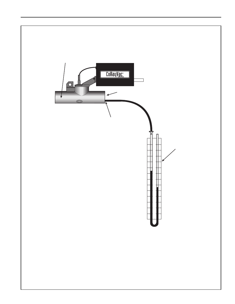
FIGURE 26: End Vent Vacuum
6
5
4
3
2
1
0
1
2
3
4
5
6
Manometer
Insert tubing
about 6" (15cm)
into end vent.
Combustion Chamber
at end burner position
End Vent
Approximate reading after adjusting
VFD frequency setting and/or
damper couplings. ( 2.5"-3" wc)
~~