Figure 27: possible damper couplings’ locations, Ure 27 – Roberts Gorden 10081601NA Rev H 12/11 User Manual
Page 52
ROBERTS GORDON
®
ULTRAVAC™ C
ONTROLLER
I
NSTALLATION
M
ANUAL
46 of 62
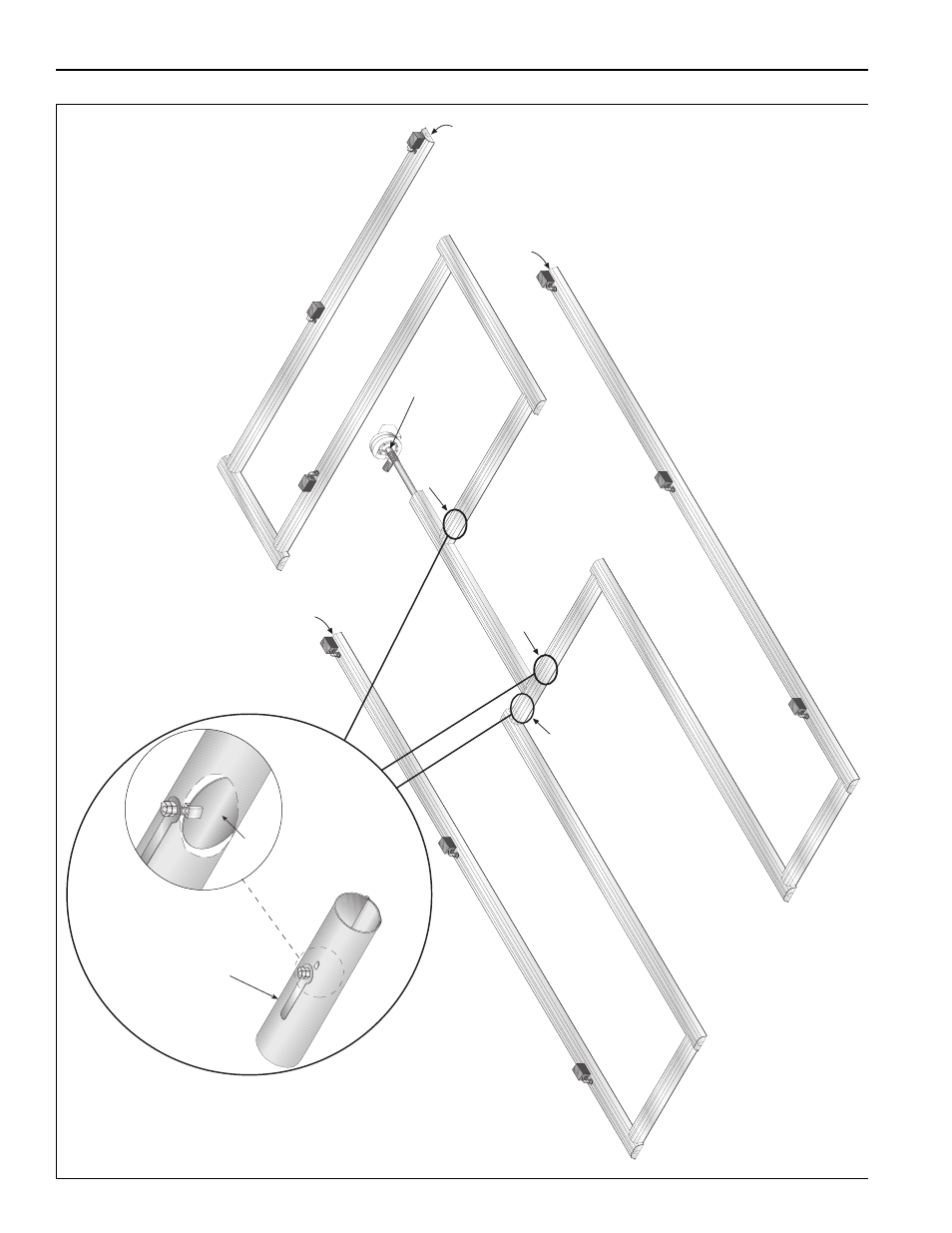
FIGURE 27: Possible Damper Couplings’ Locations
Damper Couplin
g
Damper
NOTE:
Damper settin
g
w
ill vary
Zone 1
Zone 2
Zone 3
Zone 1 End
Vent
Zone 3 End
Vent
Zone 2 End
Vent
Zone 1 Damper Couplin
g
Zone 2 Damper Couplin
g
Zone 3 Damper Couplin
g
Pump Damper