Set motor command value, Set accessory output – RoboteQ Dual Channel Digital Motor Controller AX500 User Manual
Page 108
Serial (RS-232) Controls and Operation
108
AX500 Motor Controller User’s Manual
Version 1.9b. June 1, 2007
Set Motor Command Value
Description:
Send a speed of position value from 0 to 127 in the forward or reverse direction for a given
channel. In mixed mode, channel 1 value sets the common forward and reverse value for
both motors, while channel 2 sets the difference between motor 1 and motor 2 as required
for steering. In all other modes, channel 1 commands motor 1 and channel 2 commands
motor 2.
Syntax:
!Mnn
Where M=
A: channel 1, forward direction
a: channel 1, reverse direction
B: channel 2, forward direction
b: channel 2, reverse direction
Where nn=
Speed or position value in 2 Hexadecimal digits from 00 to 7F
Examples:
!A00
channel 1 to 0
!B7F
channel 2, 100% forward
!a3F
channel 1, 50% reverse
Notes:
The hexadecimal number must always contain two digits. For example, !a5 will not be
recognized and the controller will respond with a “-” to indicate an error. The proper com-
mand in this case should be !a05.
Set Accessory Output
Description:
Turn on or off the digital output line on the 15-pin connector. See “AX500’s Inputs and Out-
puts” on page 48 for details on how to identify and wire these signals.
Syntax:
!M
Where:
M=
c: output C off
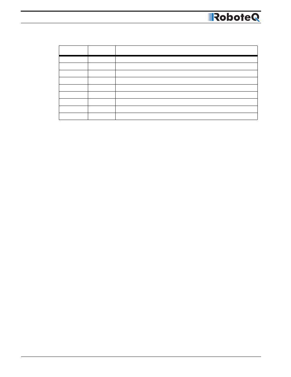
C: output C onExamples:
!C
Command
Turn Accessory Output C n
!c
Command
Turn Accessory Output C Off
?a or ?A
Query
Read Battery Amps
?v or ?V
Query
Read Power Level applied to motors
?p or ?P
Query
Read Analog Inputs 1 and 2
?r or ?R
Query
Read Analog Inputs 3 and 4
?m or ?M
Query
Read Heatsink Temperature
?e or ?E
Query
Read Battery and Internal Voltage
?i or ?I
Query
Read Digital Inputs
TABLE 17. Controller’s basic Commands and Queries
Command
Type
Description