Assembly – RIDGID EB44241 User Manual
Page 16
16
7/8 in. o.d.
washer
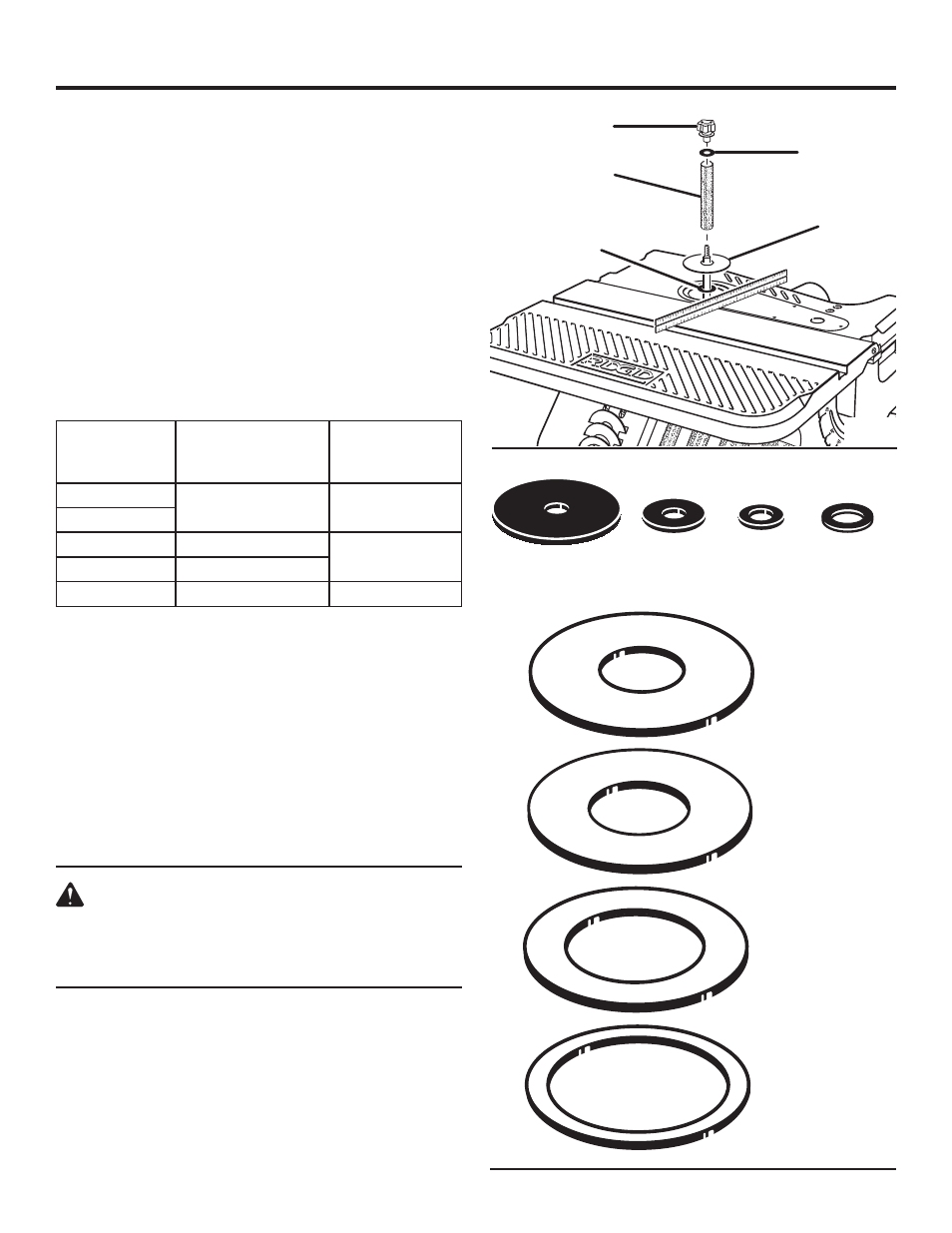
INSTALLING SANDING SLEEVES FOR THE
1/2 IN. DIAMETER SANDING DRUM
See Figure 15.
Remove the fan and clean sawdust from inside table
recess.
Slide the fan onto the motor shaft (vanes face down) align-
ing slot with roll pin.
The fan is used with all sanding
operations.
Install 1/ in. I.D. washer over motor shaft.
Install the throat plate.
Use a straight edge as shown to make sure the table
insert is flush with the table. If necessary, adjust the set
screws in the table insert with the 3/3 in. hex “L” wrench
provided.
ASSEMBLY
Position 15/16 in. I.D. throat plate into the table recess.
Locate 1/ in. sanding sleeve and slide it on the spindle.
(Rubber drum is not used.)
Install the upper spindle washer and tighten the knob.
Do not overtighten.
NOTE: Knob turns counterclockwise to tighten.
Plug power cord into the power source and install the
yellow switch key.
SELECTION OF THROAT PLATE INSERTS AND
UPPER SPINDLE WASHERS
See Figure 16.
WARNING:
Using the wrong throat plate throat plate may per-
mit small pieces of wood or finger tips to become
wedged between the abrasive surface and the
insert.
NOTE: Use the smallest throat plate that will fit over the
drum.
NOTE: Use the largest upper spindle washer that will not
protrude past sanding sleeve.
1/2 in.
sandinG
sleeve
knob
5/8 in. o.d.
washer
15/16 in. i.d.
throat Plate
5/8 in. o.d.
washer
1-3/4 in. o.d.
washer
15/16 in. i.d.
throat Plate
1-3/16 in. i.d.
throat Plate
1-11/16 in. i.d.
throat Plate
2-3/16 in. i.d.
throat Plate
Fig. 15
Fig. 16
1/2 in. i.d.
washer
1/2 in. i.d.
washer
Sanding
Sleeve
Diameter
Throat plate Insert
Opening Inside
Diameter (I.D.)
Upper Spindle
Washer Outside
Diameter (O.D.)
1/ in.
15/16 in.
5/8 in.
3/4 in.
1 in.
1-3/16 in.
7/8 in.
1-1/ in.
1-11/16 in.
in.
-3/16 in.
1-3/4 in.