Assembly, Fig. 13 fig. 14 – RIDGID EB44241 User Manual
Page 15
15
1
1
2
/
1
3
4
/
1
2
/
45
°
30
°
15
°
0
°
2
P
U
L
L
ON
I
P
U
S
H
OFF
O
REMOVE
ASSEMBLY
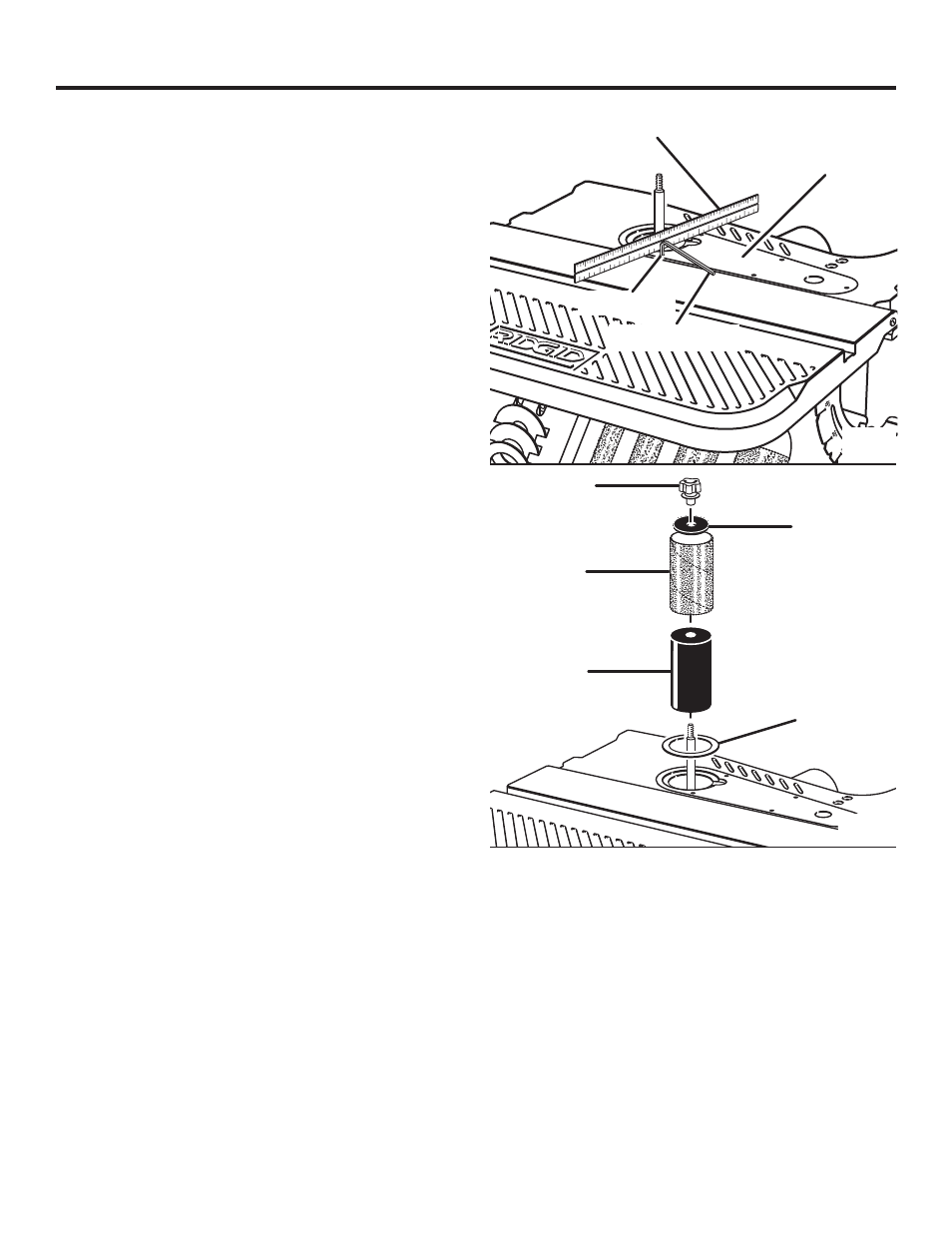
INSTALLING SANDING SLEEVES LARGER
THAN 1/2 IN. DIAMETER
See Figures 13 - 14.
Remove the fan and clean sawdust from inside table
recess.
Slide the fan onto the motor shaft (vanes face down)
aligning slot with roll pin.
The fan is used with all drums
and sleeves.
Install the table insert by sliding it over the fan.
Use a straight edge as shown to make sure the table
insert is flush with the table.
If necessary, adjust the set screws in the table insert with
the 3/3 in. hex key provided.
Slide the sanding sleeve-rubber drum onto the spindle.
NOTE: If the drum is difficult to slide over the spindle,
apply talcum powder to the spindle.
Position throat plate insert in the table recess. (See rec-
ommended throat plate insert selection area from table
on page 16). Use the smallest throat plate insert that will
fit over the drum.
Place desired sanding sleeve on correct drum.
NOTE: If the sanding sleeve is difficult to slide over the
drum, apply talcum powder to the outside surface of the
rubber drum.
Install the correct upper spindle washer and tighten the
knob. Do not overtighten.
NOTE: Knob turns counterclockwise to tighten.
Plug power cord in the power source and install the
switch key.
sandinG
sleeve
knob
washer
sandinG
drum
throat Plate
straiGht edGe
table insert
3/32 in. hex key
set sCrews
Fig. 13
Fig. 14