Wiring and schematic diagrams, Connection diagram schematic – Rheem Commercial Power Direct Vent Water heater User Manual
Page 27
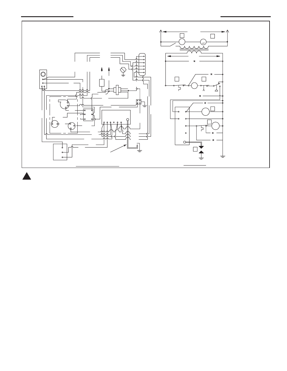
Wiring and Schematic Diagrams
1
IGNITION
LED
THERMOSTAT LED
POWER
LED
BR-3
BR-3
Y-3
BL-5
R-3
GY-1
BR-4
BR-3
BL-4
GY-1
BL-5
R-3
BR-4
BR-3
BL-4
IGNITION
CONTROL
LED
INDICATORS
MAIN VALVE
ECO
PILOT VALVE
IGNITION
THERMOSTAT
POWER
MV
MV
PV
PV
24
V
MV/P
V
GY-
2
BR-1
GN
D
PV
MV
GN
D
GAS VALVE
1
5
6
BR-2
24V
120V
PILOT
ELECTRODE ASSY.
LIMIT
CONNECTION DIAGRAM
SCHEMATIC
IGN.
MV
MV/PV
PV
GND
24
GND
MGV
BLACK
WHITE
GRAY
IGNITION CONTROL
THERMOSTAT
AND
LIMIT
TRANSFORMER
L1
L2
SWITCH
ON
OFF
Y-2
PGV
L1
L2
THERM.
W-1
120V
BL-2
5
ANY REPLACEMENT WIRE
MUST BE RATED FOR 250°C.
NORMAL OPERATION SEQUENCE
INDICATED BY BOXED NUMERALS
ECO LED
PILOT VALVE
LED
MAIN VALVE LED
C NC
NO
W
GR/YL
BK
R-1
R8
G2
BK-2
W4
BK3
BL6
BLOWER
GY-5
Y6
M
R
3
BLOWER
Y2
C
NC
PS2
PS1
Y-5
Y7
RE
LA
Y
3
4
6
5
2
R
N.C.S.W.
4
2
Figure 14. — Diagrams for units supplied with honeywell VR8304P or VR8304m gas Valve and honeywell S8600m ignition Control.
CAUTiON! label all wires prior to disconnection when servicing controls. Wiring errors can cause improper and dangerous operation. VERi-
FY PROPER OPERATiON AFTER SERViCiNg!
!
NOTICE: If any of the original wire as supplied
with this appliance must be replaced, it MUST be
replaced with 18 GA., 600V, 105°C wire or its equiv-
alent, unless otherwise noted.
27