Installation check list, Caution ! warning – Rheem Commercial Power Direct Vent Water heater User Manual
Page 13
A. Water Heater Location
❑
Close to area of vent.
❑
Indoors and protected from freezing temperatures.
❑
Proper clearance from combustible surfaces observed and
water heater not installed on carpeted floor.
❑
Air supply free of corrosive elements and flammable vapors.
❑
Provisions made to protect area from water damage.
❑
Sufficient room to service heater.
B. Water Supply
❑
Water heater completely filled with water.
❑
Water heater and piping air vented.
❑
Water connections tight and free of leaks.
C. Gas Supply
❑
Gas line equipped with shut-off valve, union, and sediment
trap/drip leg.
❑
Approved pipe joint compound used.
❑
Soap and water solution used to check all connections and
fittings for possible gas leak.
❑
Gas Company inspected installation (if required).
D. Relief Valve
❑
Discharge line run to open drain.
❑
Discharge line protected from freezing.
E. Venting
❑
All pipe connections are secure (at blower, vent terminals and for
each pipe joint connection)
❑
Vent terminals mounted properly and in correct location.
❑
Condensate tube has water in both loops.
installation Check list
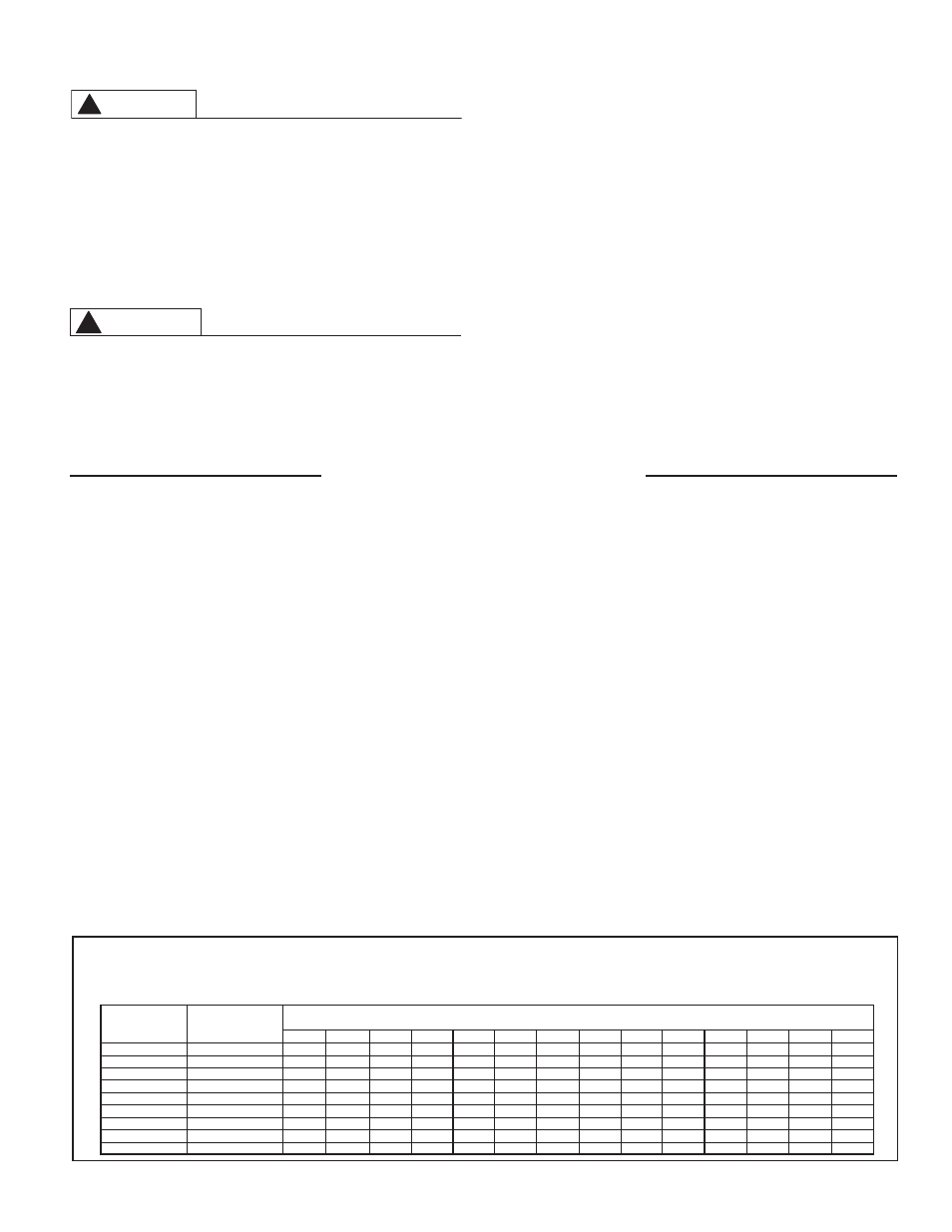
TABlE 1
maximum Capacity of Pipe in Cubic Feet of gas per hour for gas Pressures of
--------0.5 psig or less and a Pressure Drop of 0.3 inch Water Column
Based on a 0.60 Specific gravity Natural gas; if 1.5 Specific gravity l.P. gas is used, multiply capacity by 0.63
Nominal
internal
iron Pipe Size,
Diameter
inches
inches
10
20
30
40
50
60
70
80
0
100
125
150
175
200
1/2
.622
132
2
73
63
56
50
46
43
40
38
34
31
28
26
3/4
.824
278
10
152
130
115
105
6
0
84
7
72
64
5
55
1
1.04
520
350
285
245
215
15
180
170
160
150
130
120
110
100
1 1/4
1.380
1,050
730
50
500
440
400
370
350
320
305
275
250
225
210
1 1/2
1.610
1,600
1,100
80
760
670
610
560
530
40
460
410
380
350
320
2
2.067
3,050
2,100 1,650
1,450 1,270
1,150 1,050
0
30
870
780
710
650
610
2 1/2
2.46
4,800
3,300 2,700
2,300 2,000
1,850 1,700 1,600 1,500
1,400 1,250
1,130
1,050
80
3
3.068
8,500
5,00 4,700
4,100 3,600
3,250 3,000 2,800 2,600
2,500 2,200
2,000
1,850 1,700
4
4.026
17,500 12,000 ,700
8,300 7,400
6,800 6,200 5,800 5,400
5,100 4,500
4,100
3,800 3,500
Length of Pipe, Feet
13
FOR PROPER iNSTAllATiON:
•
DO NOT use solvent cement that has become
curdled, lumpy or thickened.
•
DO NOT thin solvent cement. Observe shelf
precautions printed on the containers.
•
For applications below 32°F use only low
temperature type solvent cement.
•
Appropriate solvent and cleaner must be used for
the type of vent pipe used (PVC, CPVC or ABS).
DANgER OF FiRE OR BODilY iNJURY – Solvent
cements and primers are highly flammable. Pro-
vide adequate ventilation and do not assemble
near heat source or open flame. Do not smoke.
Avoid skin or eye contact. Observe all cautions
and warnings on material containers.
6. WIRING — A polarized 120V 50/60 Hz power supply, with suitable
disconnect means, must be connected to the black and white leads
provided. The current draw by the Power Direct Vent unit is 1.5 Amps.
The water heater, when installed, must be electrically grounded in ac-
cordance with local codes, or, in the absence of local codes, with the
National Electrical Code, ANSI/NFPA 70 in the United States; or CSA
C22.1 Electrical Code, in Canada. Refer to Fig. 14 on page 26 & 27
of this manual for water heater internal wiring diagrams.
NOTICE: DO NOT use in conjunction with a GFCI.
CAUTION
!
WARNING
!