Start-up, Main burner adjustment, Gas valve adjustment – Raypak HI DELTA HD101 User Manual
Page 38
38
Check the Gas Supply Pressure
1. Slowly turn on main gas shut-off valve.
2. Read the gas supply pressure from the manome-
ter; minimum supply pressure is 4 in. WC,
recommended supply is 7 in. WC for natural gas
(minimum 11.0 in. WC for LP gas).
3. If pressure is > 14 in. WC, turn off the valve.
4. Check if the service regulator is installed and/or
adjust the service regulator.
Start-Up
Blower Adjustment
1. Connect manometer to the plugged side of the
tee.
2. Close manual firing valve.
3. Turn power on.
4. Check manometers attached to fan pressure
switch. This (LO) speed pressure reading should
be:
–0.2 in. WC for models HD101 and HD151.
–0.3 in. WC for models HD201–HD401.
If not, adjust the air shutter on the blower to attain
the correct value. (See air shutter adjustment
page 7).
5. Turn power off.
6. Reinstall rubber plug on tee.
Main Burner Adjustment
1. Turn off unit.
2. Open manual firing valve.
3. Turn on the unit, wait 15 seconds, and the igniter
should glow. There’s a sight glass to check igniter
at both ends of the heater. Gas valve should be
open after 45 seconds.
4. If burner does not light on first trial. It will retry, up
to 3 times.
5. Main burner ignition – check manifold gas pres-
sure at gas valve manifold pressure tap. (See gas
valve details on page 7) This should read 3.0 in. ±
0.3 in. WC (HI) and 1.0 in. ± 0.1 in. WC (LO) for
natural gas or 10.0 in. ± 0.1 in. WC (HI), and 3.5
in. ± 0.1 in. WC (LO) for propane gas.
6. If the pressure reading differs by more than the tol-
erance given, adjust the gas valve accordingly.
See gas valve adjustment section below for
instructions.
Gas Valve Adjustment
Honeywell Gas Valve
1.
While the heater is running, remove plastic cap
located behind ON/OFF knob.
2. Locate the HI or LO screw to adjust.
3. Using a small flat screwdriver, turn clockwise to
increase and counterclockwise to decrease mani-
fold pressure. See nominal gas valve manifold
settings in Table N above.
4. Replace plastic cap when pressure is set.
White Rodgers Gas Valve
1. While the heater is running, locate the HI or LO
cap located adjacent to ON/OFF switch.
2. Remove the appropriate cap.
3. Using a flat screwdriver, turn clockwise to increase
and counterclockwise to decrease manifold pres-
sure. See nominal gas valve manifold settings
above.
4. Replace cap(s) when pressure is set.
Invensys (Model HD401 Natural
Only)
1. Turn heater off.
2. Locate and remove the Torx tamper resistant
screw. (Shown in Fig. 30)
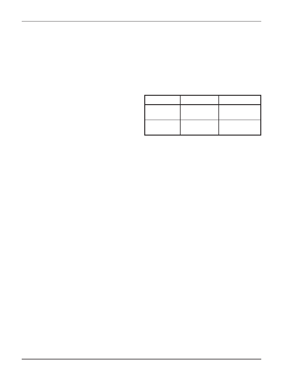
Firing Stage
Natural Gas
Propane Gas
HI or ON/OFF
2.9–3.1 in. WC
9.9–10.1 in. WC
LO
0.9–1.1 in. WC
3.4–3.6 in. WC
Table N: Manifold Pressures