10 external trigger signal – Renesas MCU Board for 4513/4514 Group MCUs M34514T-MCU User Manual
Page 36
( 36 / 42 )
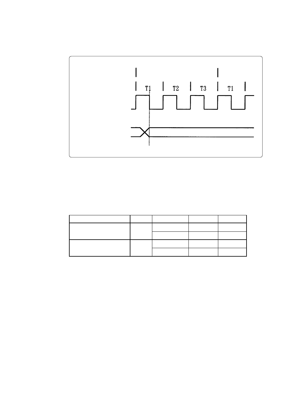
5.10 External Trigger Signal
(1) External trigger signal input timing
The latch timing of the external trigger signal is shown in Figure 5.3.
Figure 5.3 Latch timing of external trigger signal
(2) External trigger signal input characteristics
Trigger breaks work according to the condition (leading edge/trailing edge) of signals input from
the external trace cable. The external trigger signals of the trace points and the external trigger
signals of the break points use the same signals. The input characteristics of the external trigger
signals are shown in Table 5.3 below. See the table before using external trigger signals.
Table 5.3 External trigger signal input characteristics
Item
H-level input voltage
L-level input voltage
V
IH
V
IL
V
CC
= 2.0 V
V
CC
= 4.5 V
V
CC
= 4.5 V
V
CC
= 2.0 V
-
-
-
-
Symbol
Voltage
Maximum
Minimum
0.5 V
1.35 V
1.5 V
3.15 V
System clock
X
IN
External trigger signal
TRIG
Instruction
Next Instruction
- Single-Chip Microcomputer M34551T2-MCU (42 pages)
- M3T-FLX-80NRA (6 pages)
- 70 (162 pages)
- M16C/30P (102 pages)
- PROM Programming Adapter PCA7427G02 (20 pages)
- R0E572110CFK00 (40 pages)
- H8/325 Series (20 pages)
- Single-Chip Microcomputer H8/36079 (27 pages)
- Direct Dummy IC M3T-DIRECT100S (4 pages)
- M3A-2152 (95 pages)
- PCA7755D (6 pages)
- M16C/6N5 (106 pages)
- SH7085 (50 pages)
- QFP-144 (23 pages)
- H8/3834 Series (22 pages)
- RSKM16C62P (3 pages)
- H8/33937 (22 pages)
- Single-Chip Microcomputer H8SX/1622 (5 pages)
- E6000 (29 pages)
- PCA7400 (18 pages)
- PCA4738FF-64 (20 pages)
- SuperH HS7339KCU01HE (43 pages)
- M16C FAMILY (103 pages)
- PCA7412F-100 (20 pages)
- 4513 (210 pages)
- M34551E8FP (16 pages)
- Dummy IC M3T-SSOP36B-450 (4 pages)
- Emulation Pod M30100T3-RPD-E (52 pages)
- Converter Board for M30102 M30102T-PTC (4 pages)
- SH7145 (31 pages)
- HS1653ECN61H (36 pages)
- Converter Board R0E521276CFG00 (4 pages)
- PCA7302E1F-80 (18 pages)
- H8/3814 Series (21 pages)
- H8S/2646 Series (20 pages)
- SuperHTM Family SH7125 Series (40 pages)
- M30262T-PTC (4 pages)
- SH7670 (82 pages)
- H8/3864 Series (20 pages)
- Emulator System M3T-MR100 (306 pages)
- 38K0 (6 pages)
- PLQP0176KB-A (40 pages)
- Direct Dummy IC M3T-DIRECT80S (6 pages)
- PCA4738L-80A (26 pages)
- Converter Board R0E5212BACFG00 (6 pages)